Advanced Simulation Module: Custom Mode for Drone CFD Analysis
Getting Started
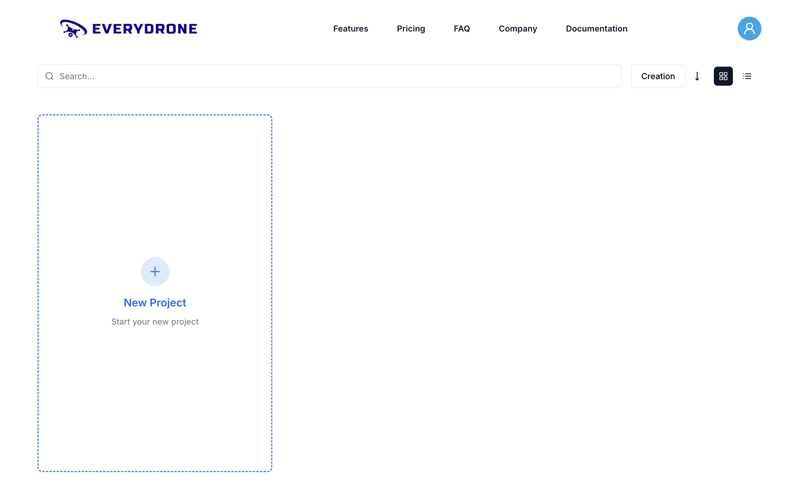
To start the Custom CFD Analysis for a drone, navigate to the Dashboard and create a new project.
1. Creating a New Project
Click on New Project to start setting up your custom simulation.
Step 1: Selecting the Drone Type
First, select the type of drone for your CFD analysis.
- Multi Rotor: A versatile with multiple propellers for precise control.
- Single Rotor: An efficient single rotor system for extended operations.
- Fixed Wing: Optimized for long-range stability and endurance.
- Hybrid VTOL: Combines vertical takeoff with fixed-wing efficiency.
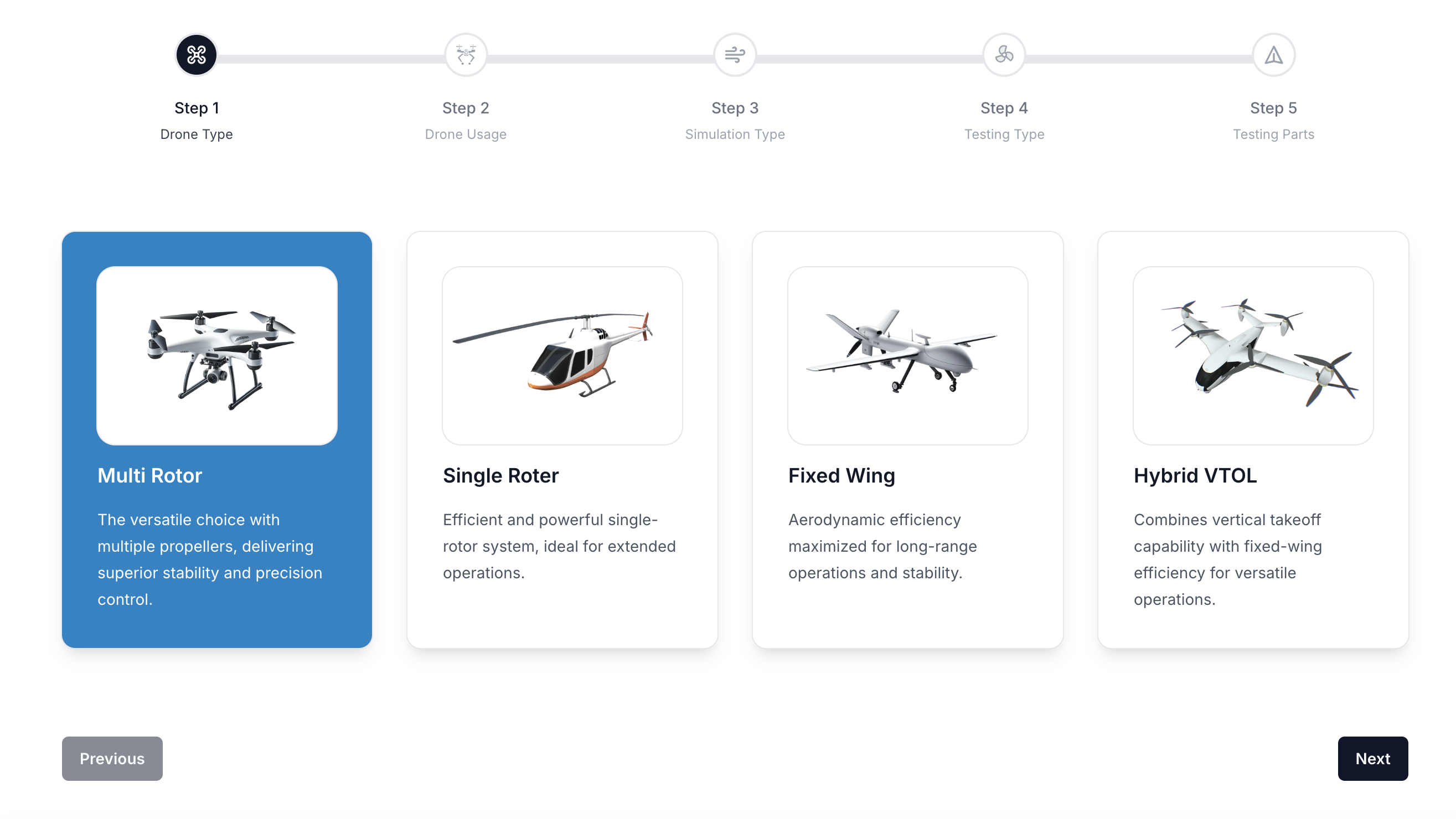
Click Next to proceed.
Step 2: Defining the Drone Usage
Next, define how the drone will be used to ensure accurate simulation results.
- Photographic Use: Optimized for aerial imaging, surveillance, and mapping.
- Delivery Purpose: Designed for efficient payload transport with autonomous navigation.
- Military & Tactical: Specialized for reconnaissance and defense applications.
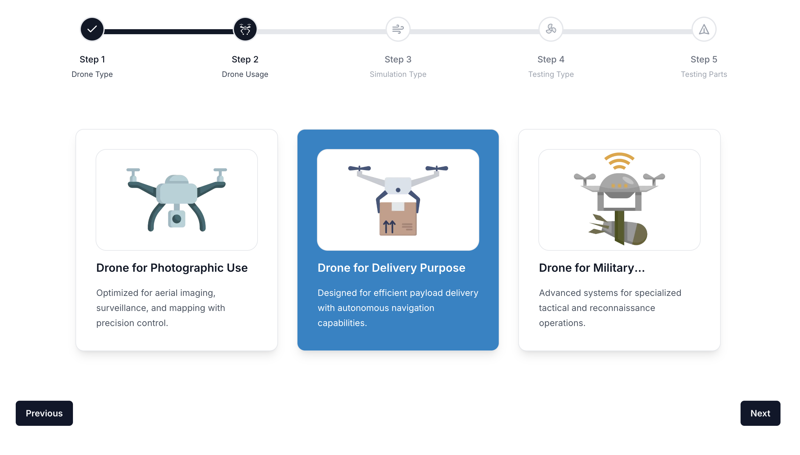
Click Next to continue.
Step 3: Selecting the Simulation Type
Choose the type of simulation to run. For this tutorial, select Fluid Dynamics.
- Structural Analysis: Tests drone frame integrity and durability.
- Fluid Dynamics: Simulates aerodynamic performance for flight optimization.
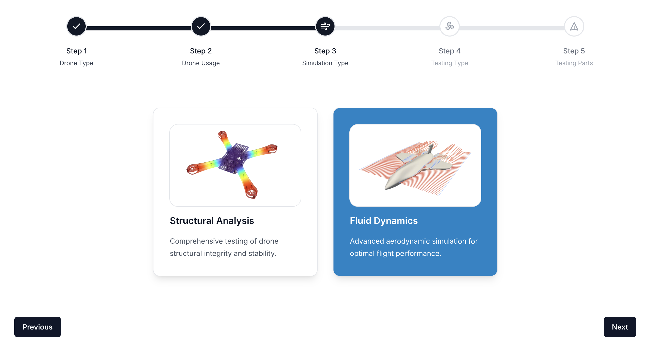
Click Next to continue.
Step 4: Selecting the Testing Type
For Custom Mode, select Integration Testing to evaluate the aerodynamic performance of the entire drone system.
- Integration Testing: Complete system evaluation for overall flight performance.
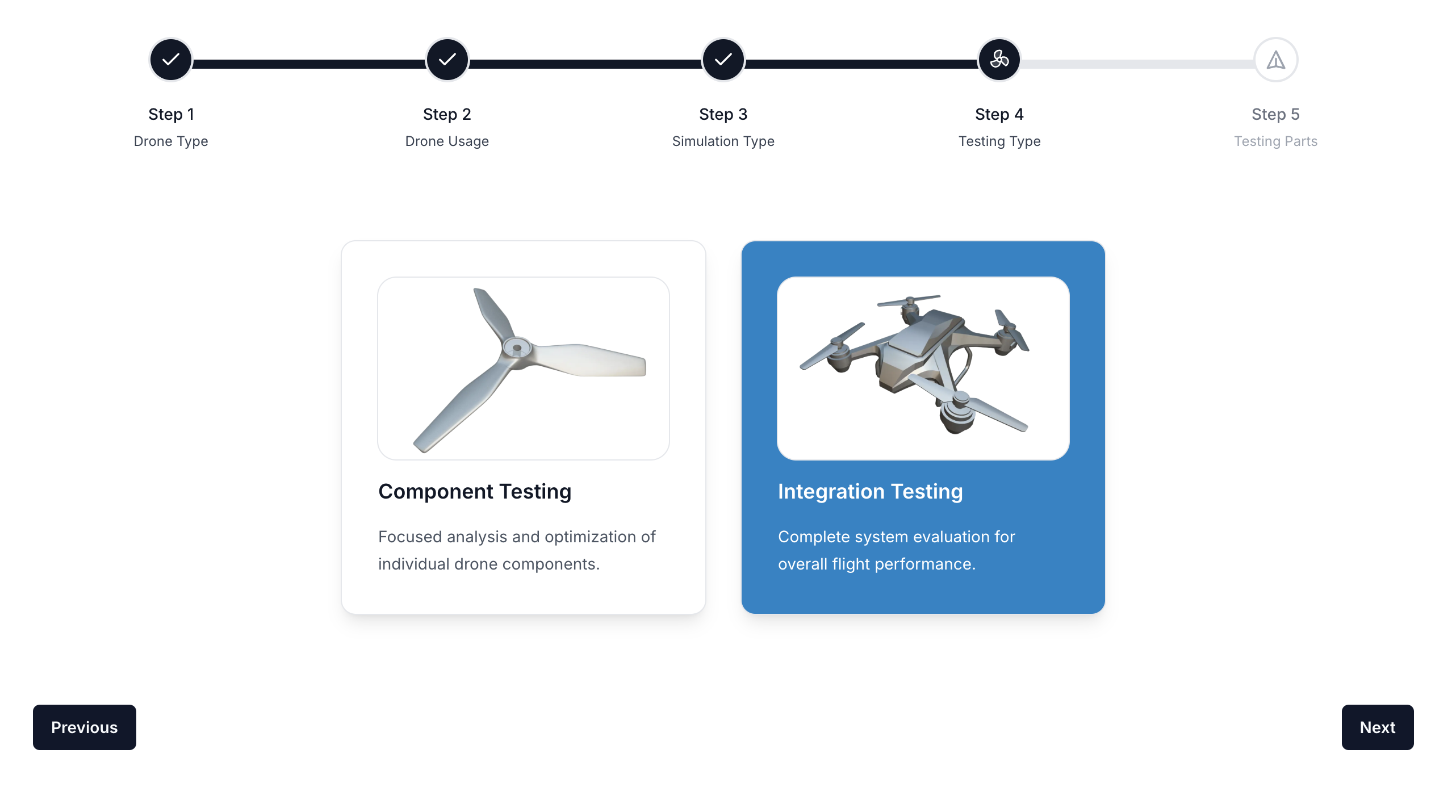
Click Next to proceed.
Step 5: Enabling Custom Simulation Mode
Select Custom Settings to manually define simulation parameters.
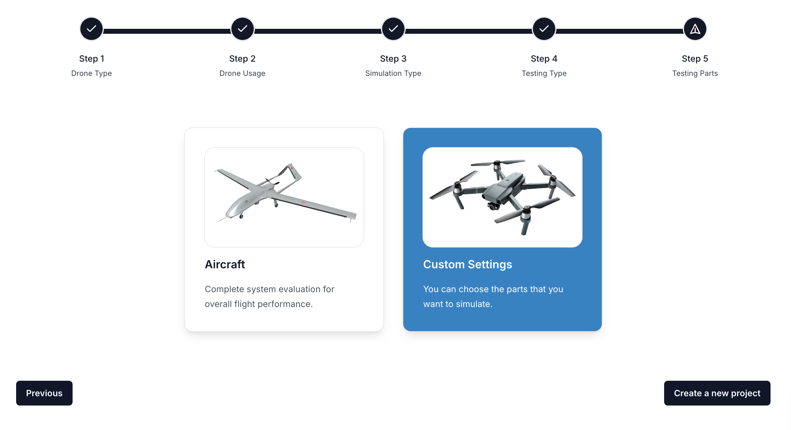
Click Create a New Project to proceed.
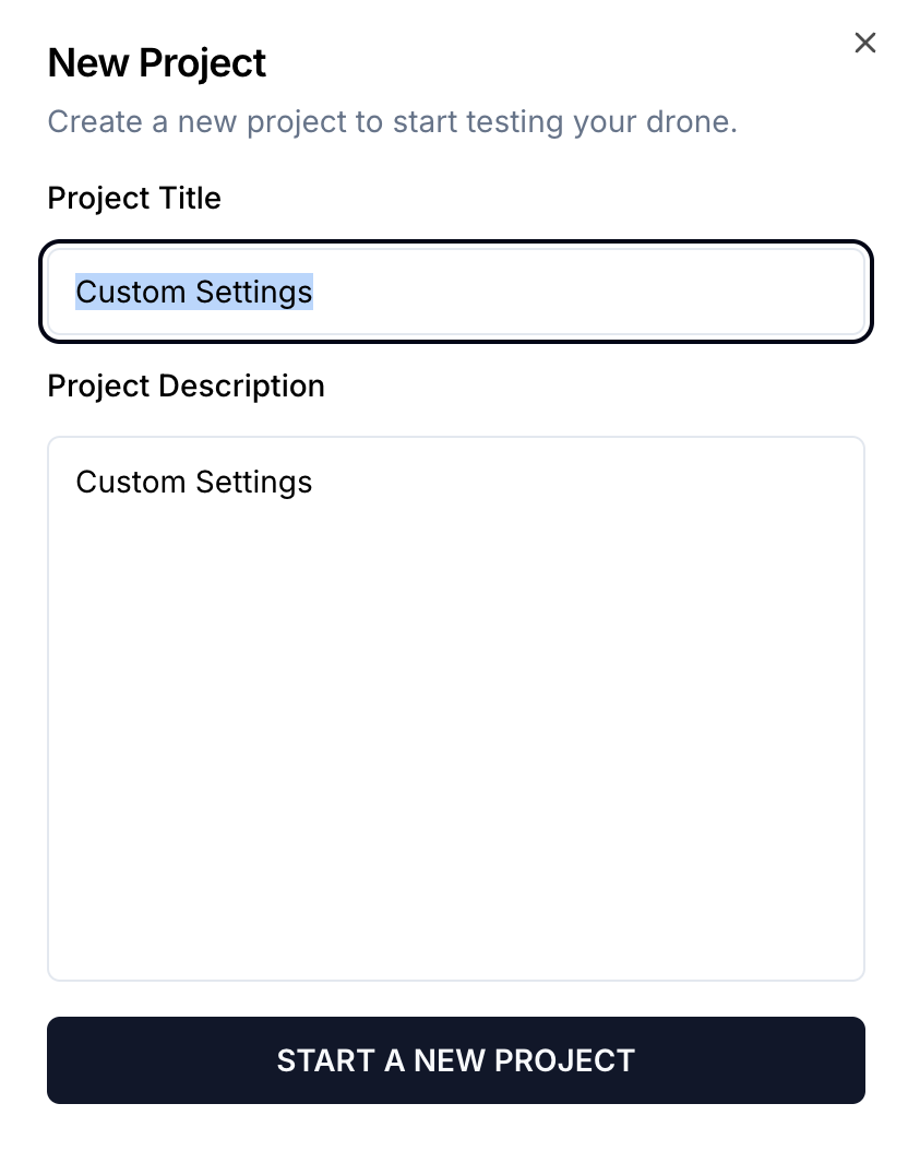
Step 6: Setting Up Project Details
Enter a Project Title and Description, then click Start a New Project.
Step 7: Custom Simulation Workflow
The workflow panel offers a step-by-step guide for setting up the custom CFD analysis.

Step 8: Importing CAD Model
Import the drone geometry CAD file to begin the simulation process.
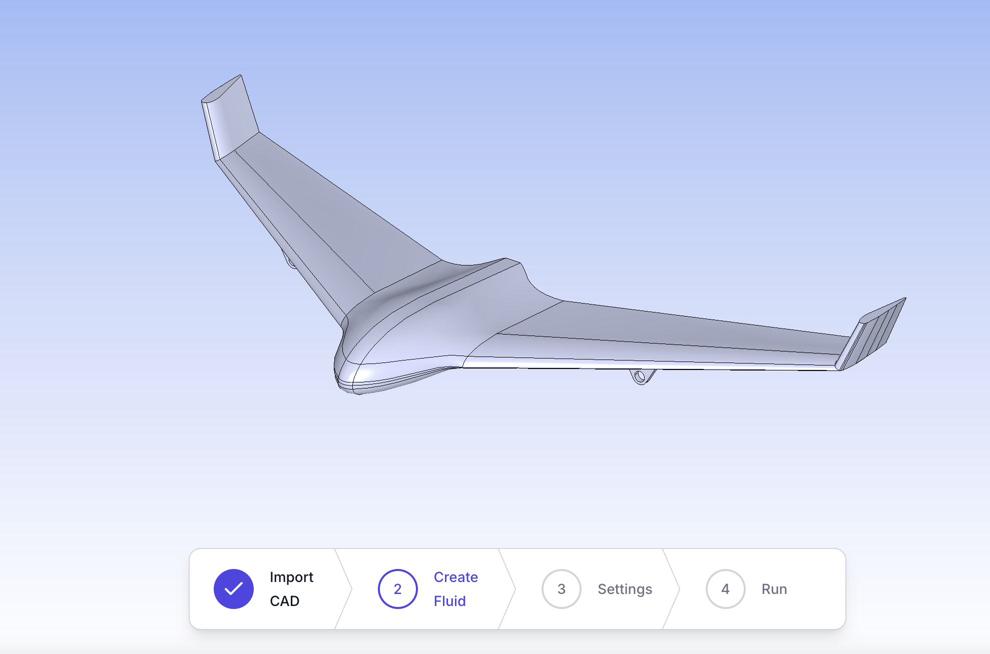
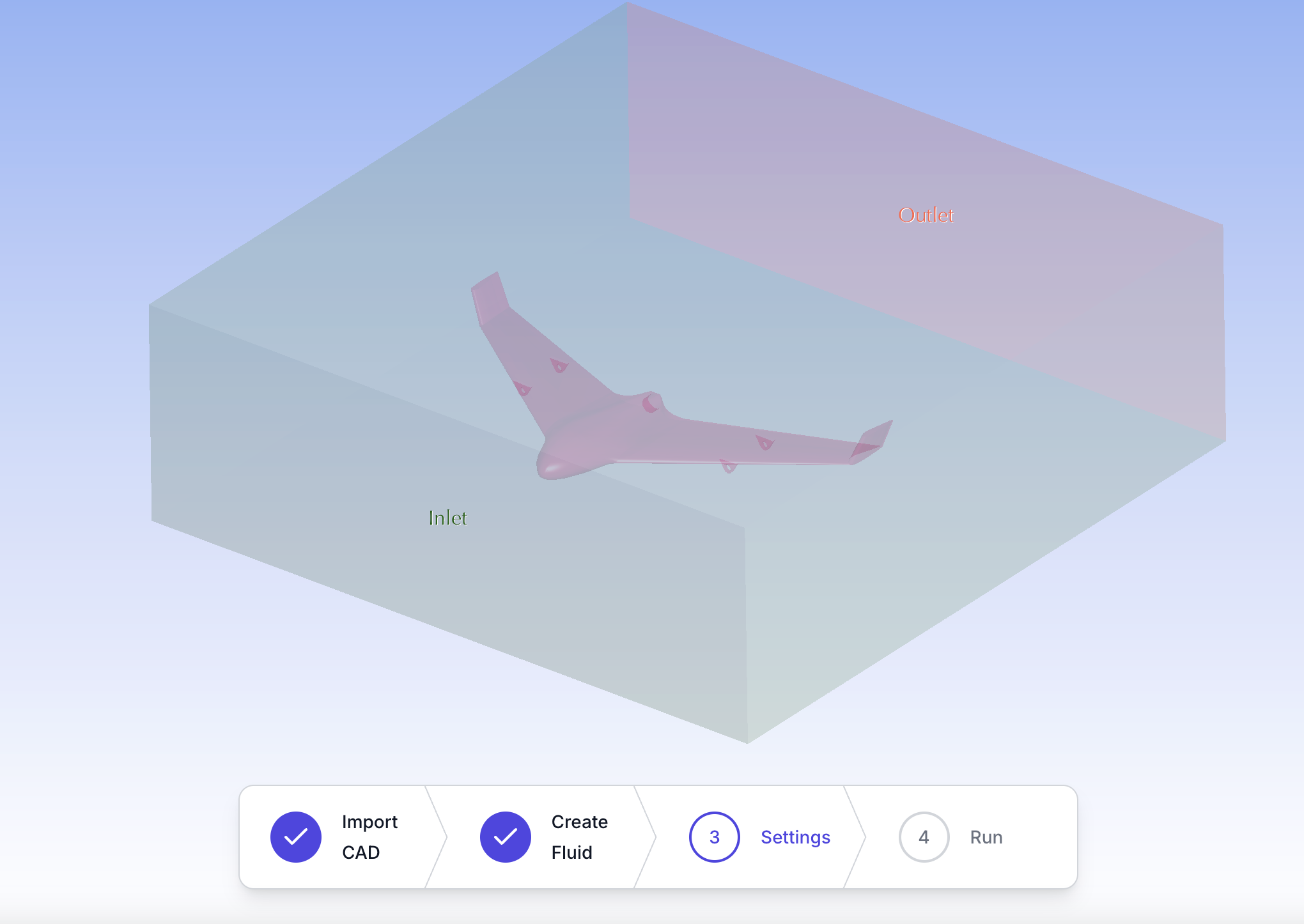
Step 9: Creating the Fluid Domain
Define the fluid region around the drone to simulate airflow behavior.
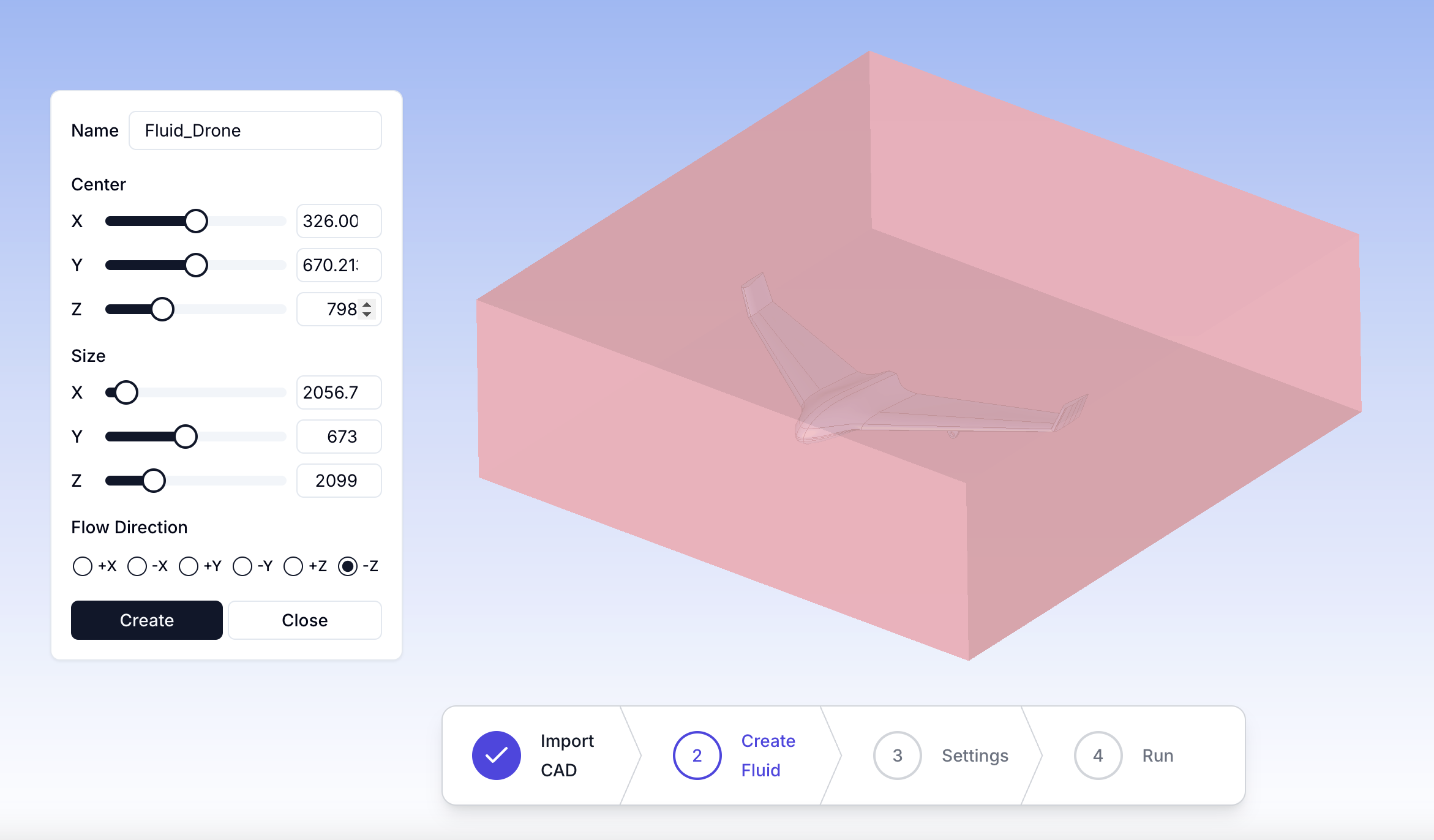
Once the parameters are set, finalize the fluid domain setup.
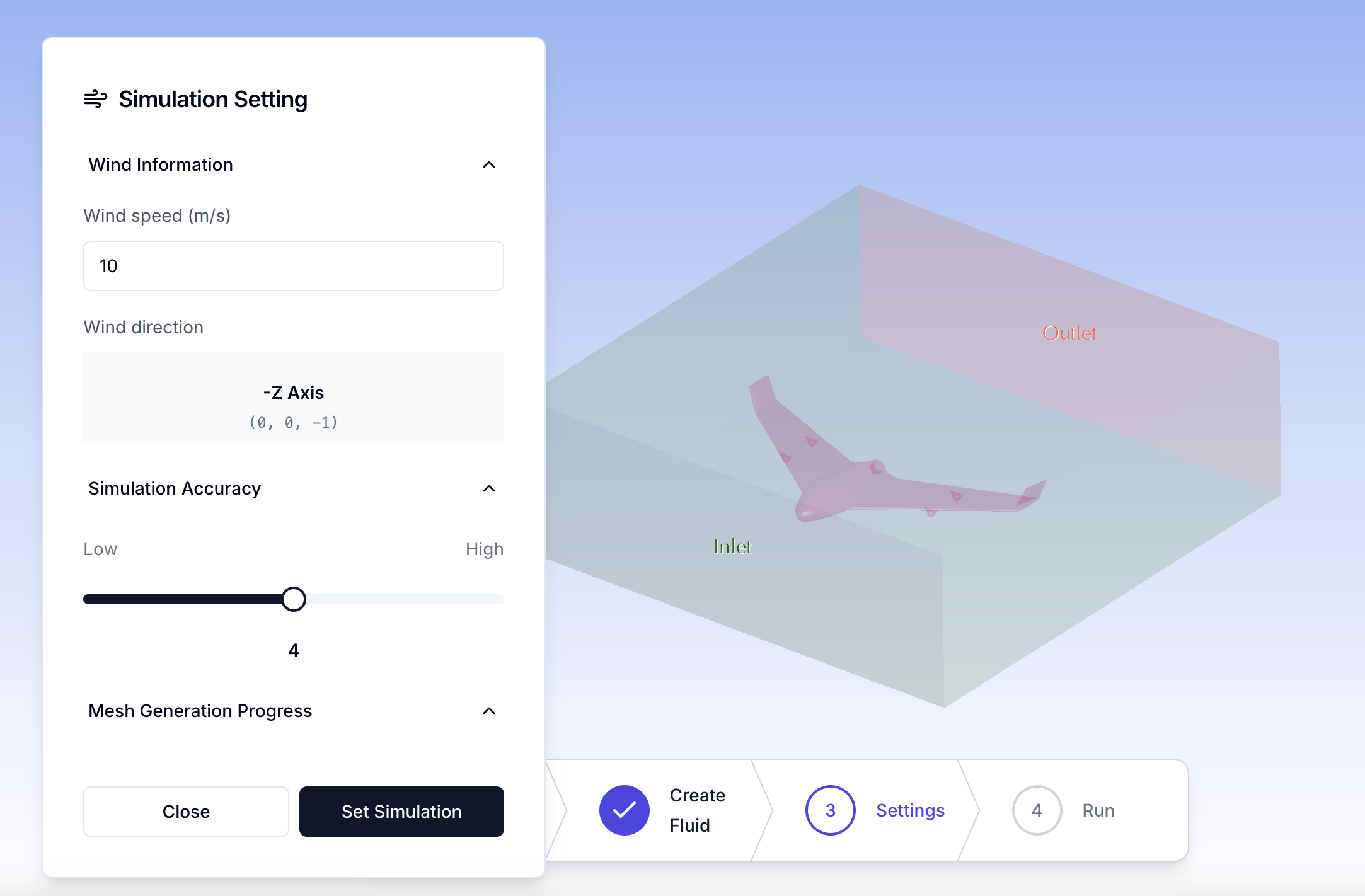
Step 10-11: Configuring Simulation Settings & Generating Mesh
Set the wind speed, direction, and accuracy based on the predefined fluid region settings. The wind direction is automatically inherited from the fluid region configuration. Higher Simulation Accuracy increases the mesh density, improving result precision.
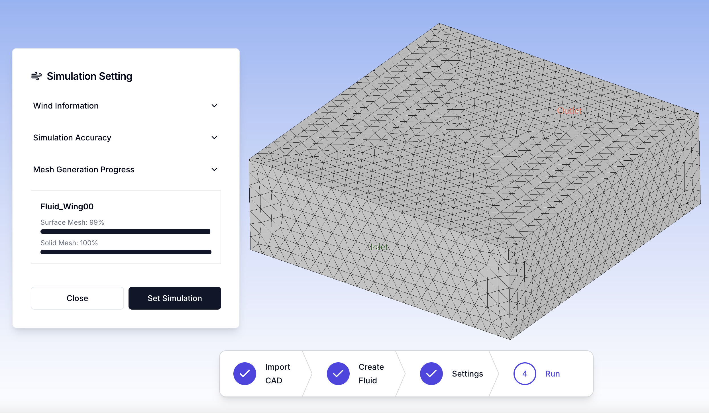
Generate the computational mesh to refine simulation accuracy.
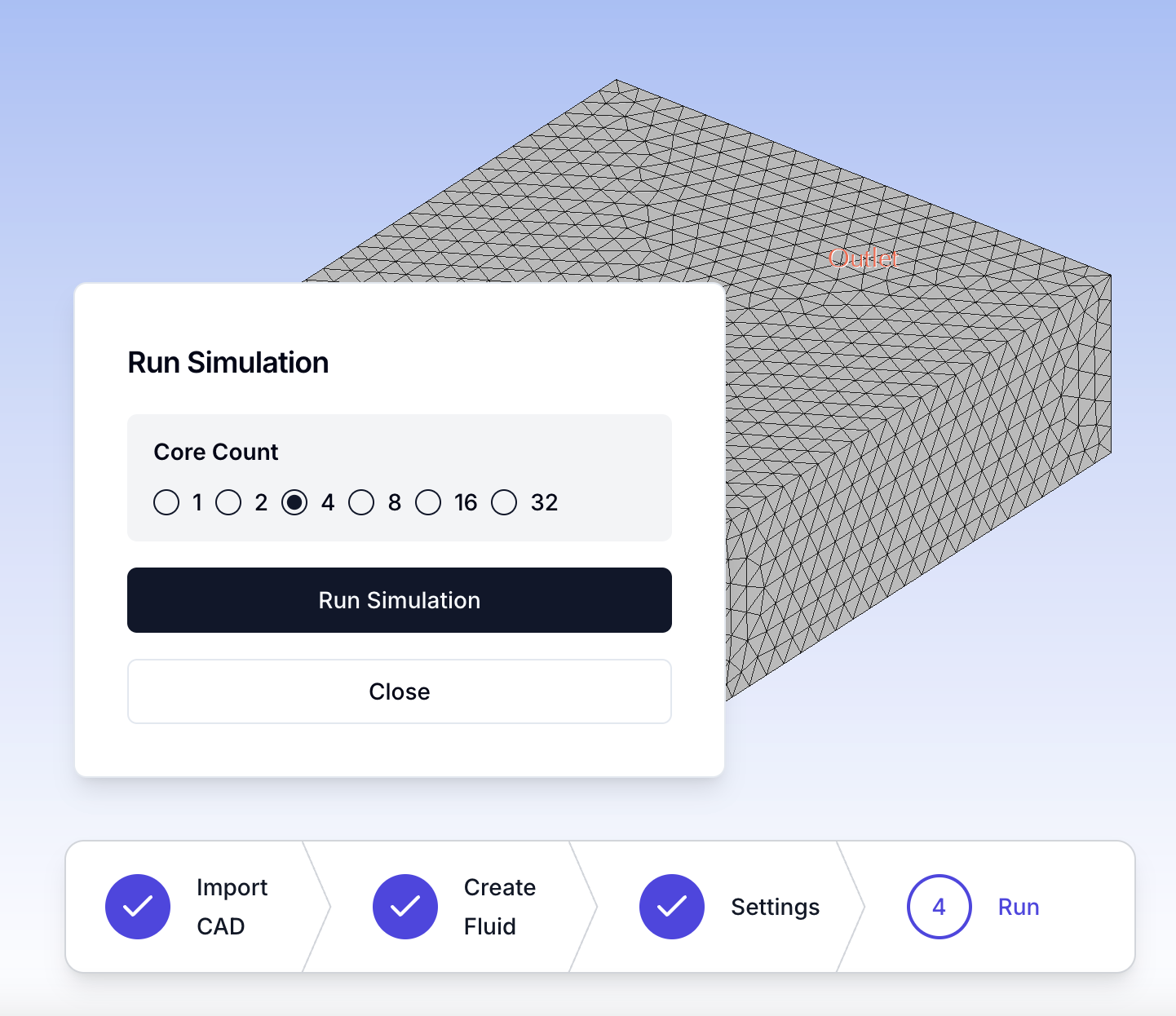
Step 12: Running the Simulation
Select the number of CPU cores and start the simulation.
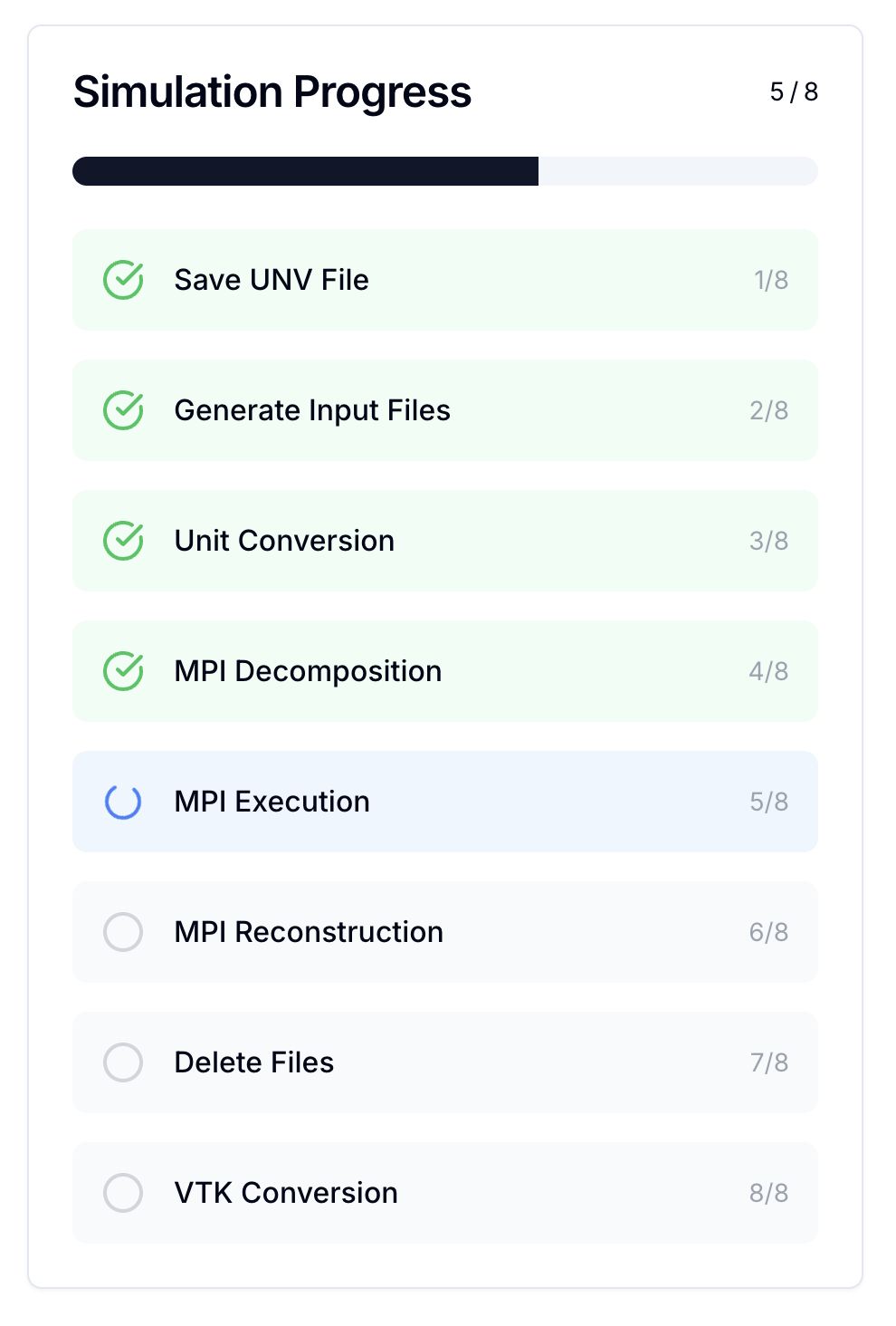
Monitor the progress as the simulation executes.
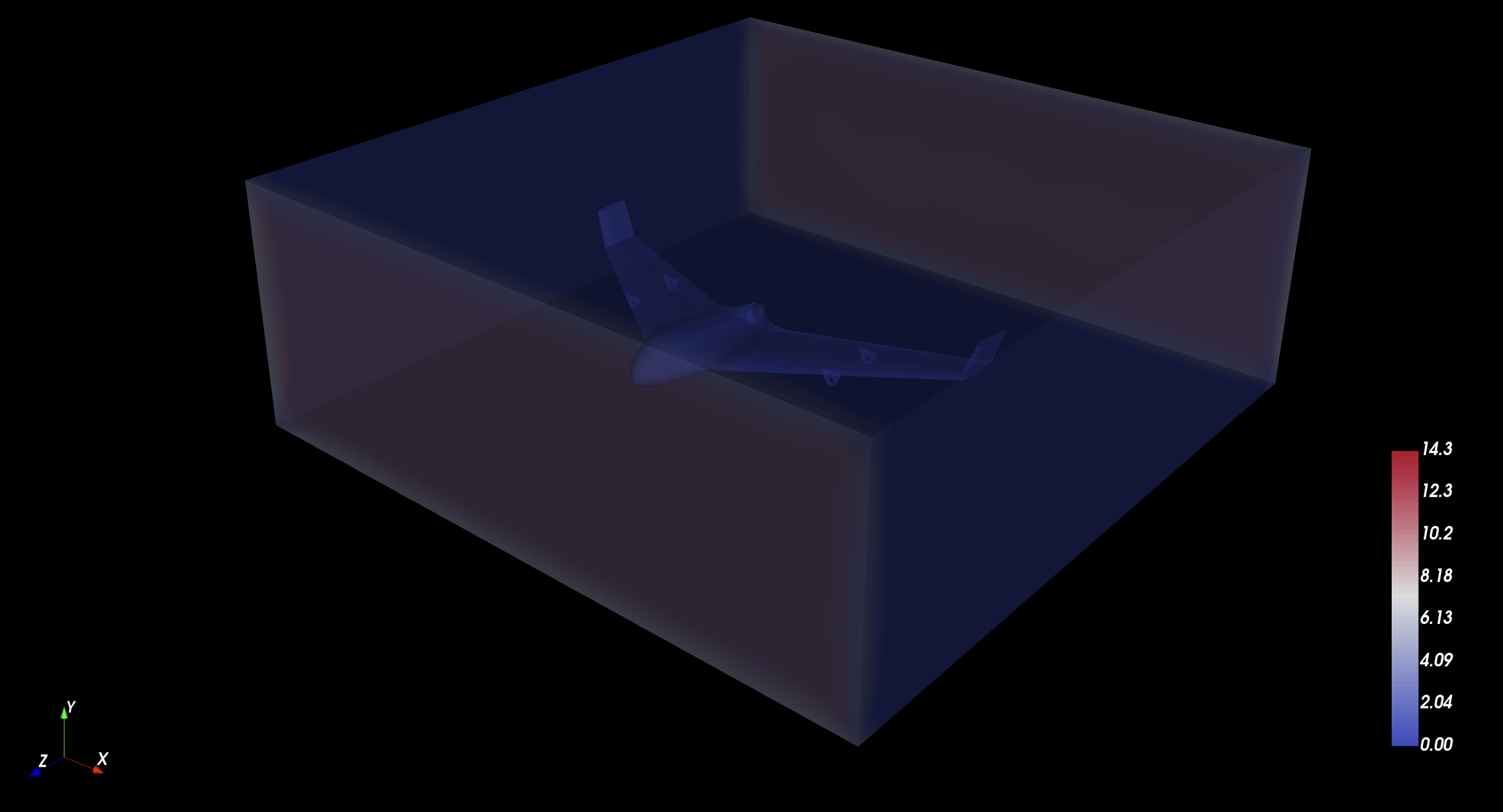
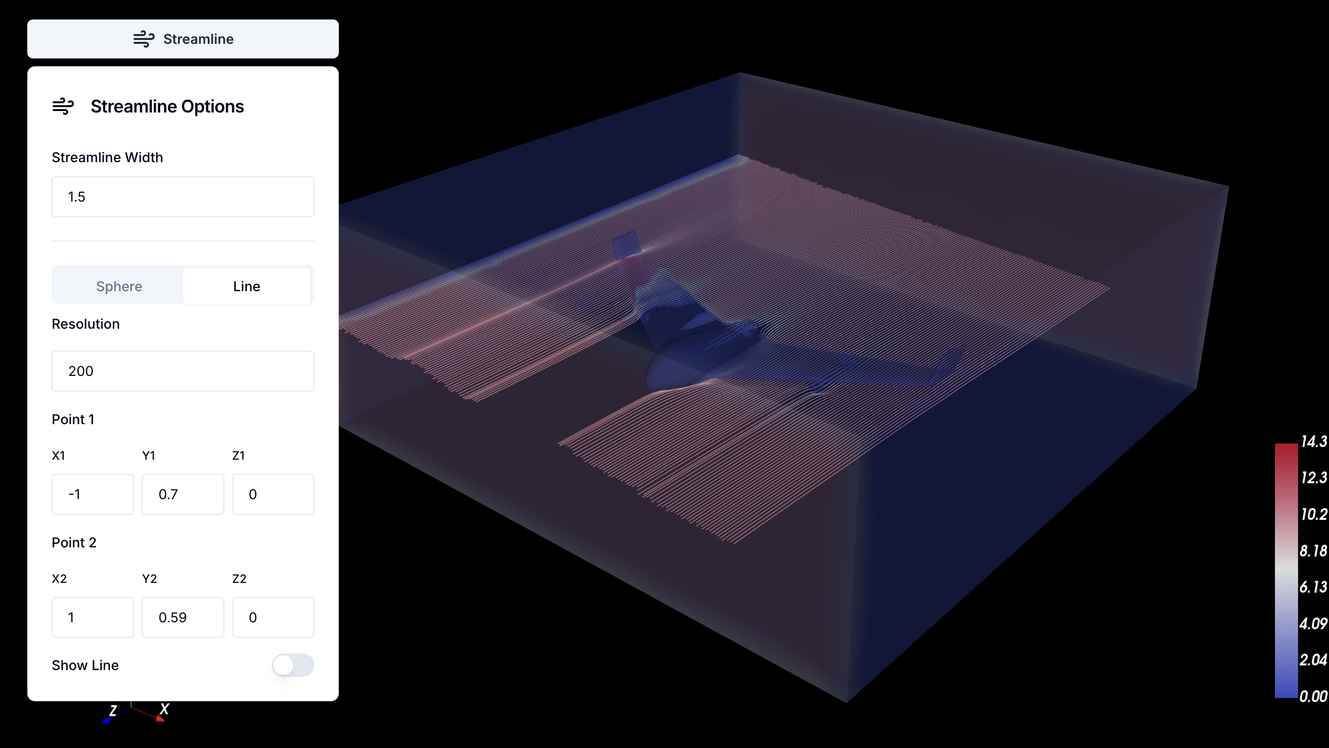
Step 13: Visualizing Results
Analyze the velocity field, pressure distribution, turbulence characteristics, and aerodynamic behavior.
View detailed result data and parameter settings.
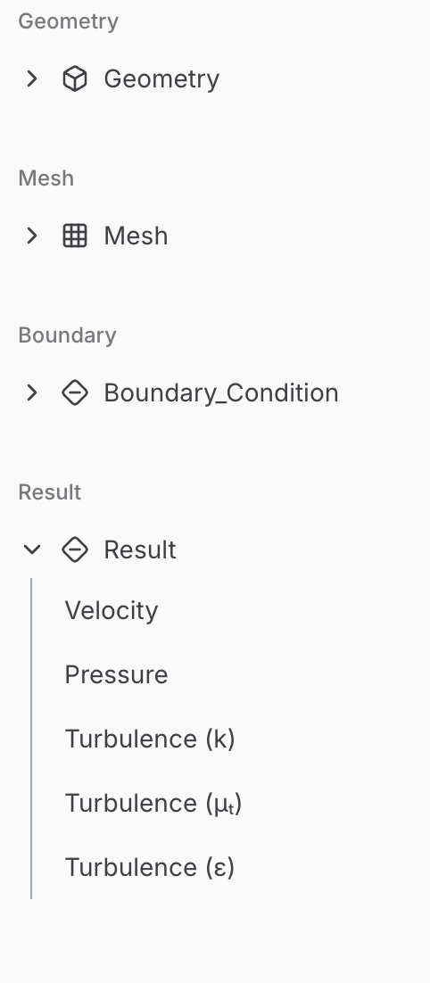
Enable streamlines to visualize the airflow over the drone. Users can freely choose between Sphere or Line streamline modes. This option becomes available when selecting Velocity in the results tree on the left panel.
Final Steps
Once the analysis is complete, extract insights from the CFD data, optimize the drone’s design, and refine aerodynamic efficiency for improved performance.