Advanced Simulation Module: Propeller CFD Tutorial
Getting Started
To start the Propeller CFD Analysis, go to the Dashboard and create a new project.
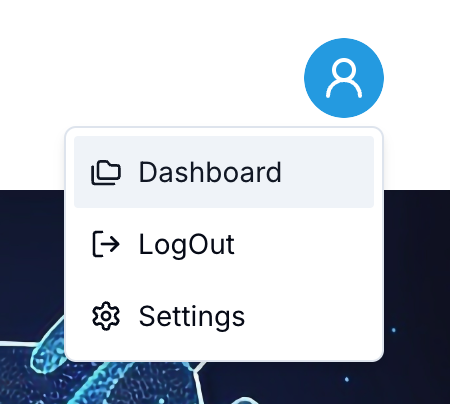
Accessing the Dashboard
Click the user icon in the top right corner and select Dashboard from the dropdown menu.
From the Dashboard, click New Project to initiate the design and simulation workflow.
Step 1: Selecting the Drone Type
The first step in the wizard is selecting the drone type that best suits your design.
- Multi Rotor: Versatile with multiple propellers for precise control.
- Single Rotor: Powerful, efficient, ideal for extended operations.
- Fixed Wing: Optimized for long-range stability and efficiency.
- Hybrid VTOL: Combines vertical takeoff with fixed-wing efficiency.
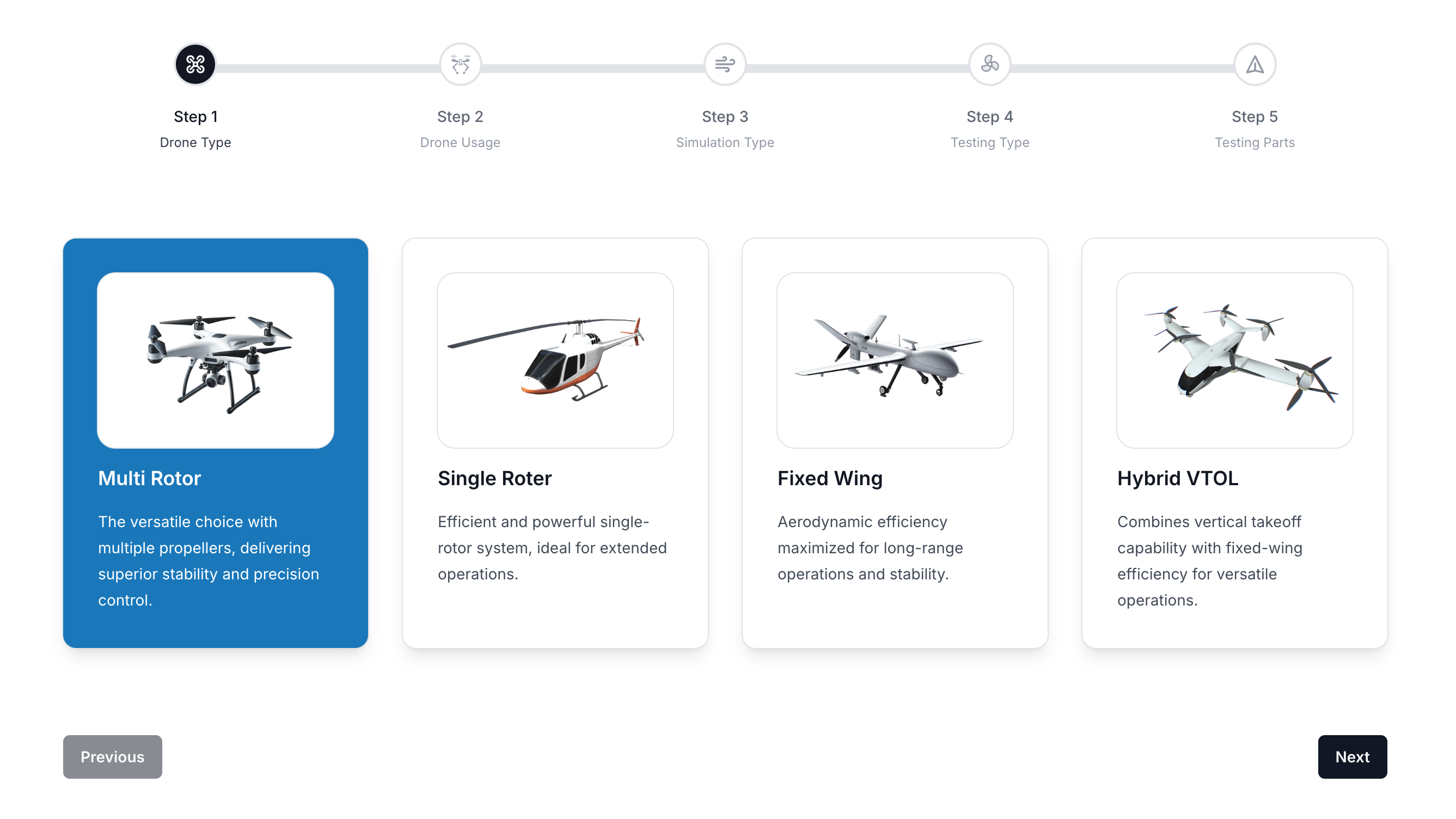
Select the desired drone type and click Next to proceed.
Step 2: Defining the Drone Usage
Next, define the primary usage scenario for the drone to tailor the simulation accordingly.
- Photographic Use: Optimized for aerial imaging and mapping.
- Delivery Purpose: Designed for payload transportation with autonomous navigation.
- Military & Tactical: Specialized systems for reconnaissance and defense applications.
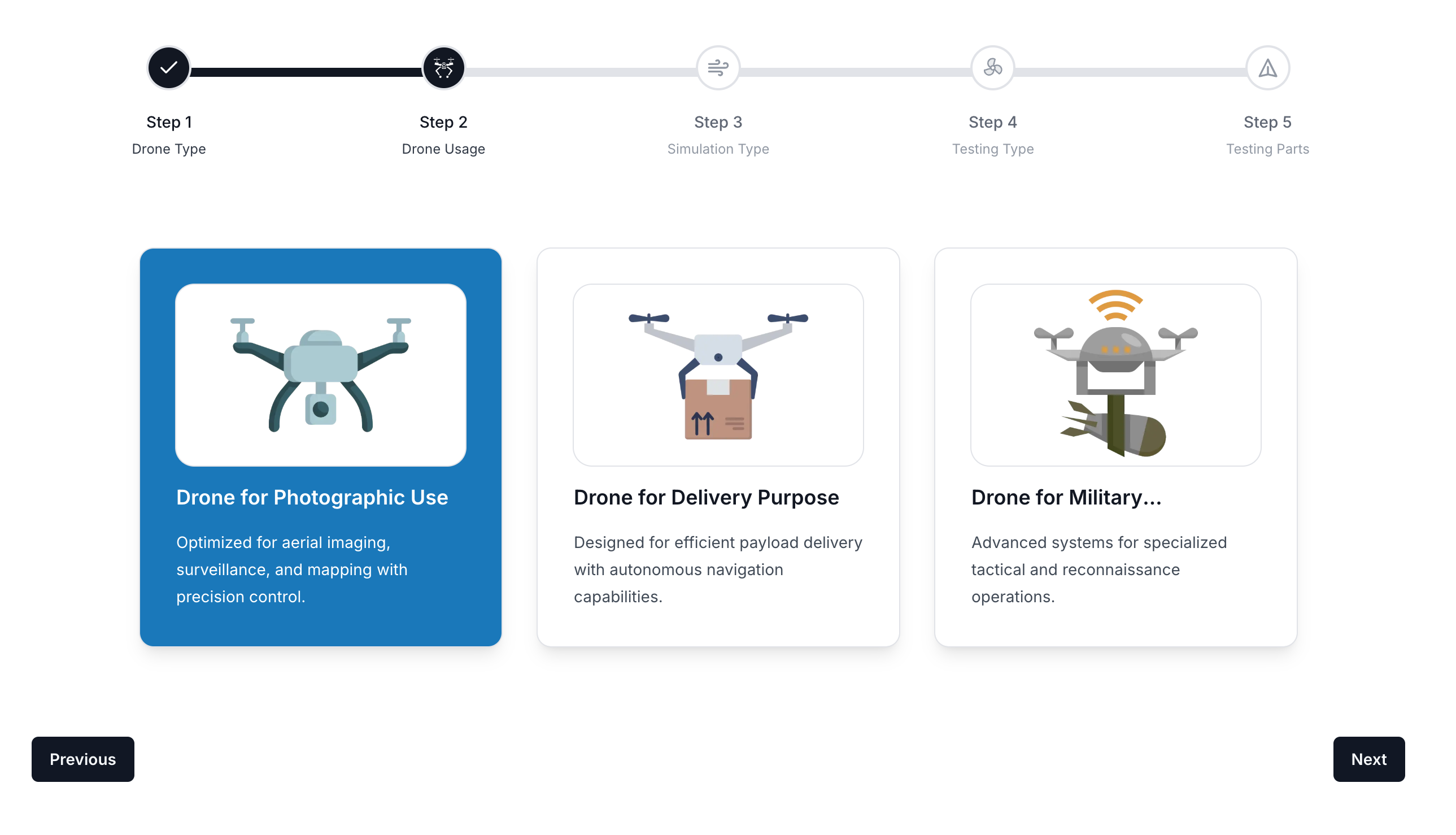
Choose the relevant usage case and click Next to continue.
Step 3: Selecting the Simulation Type
In this step, choose the type of simulation to run. Since this tutorial focuses on Propeller CFD, select Fluid Dynamics.
- Structural Analysis: Evaluates drone frame integrity and durability.
- Fluid Dynamics: Simulates aerodynamic performance for optimal flight efficiency.
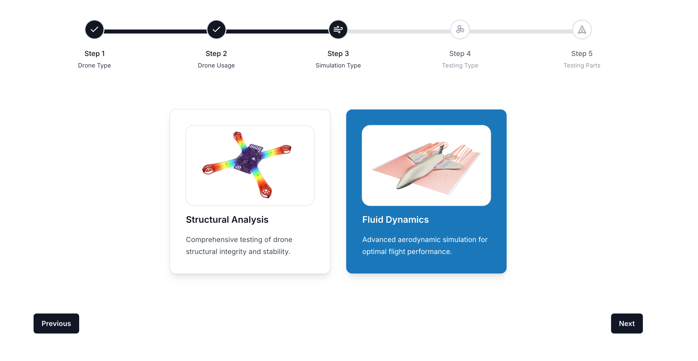
Click Next after selecting the Fluid Dynamics option.
Step 4: Integrating Components
At this stage, the workflow will guide you through integrating necessary drone components, ensuring compatibility before running the simulation.
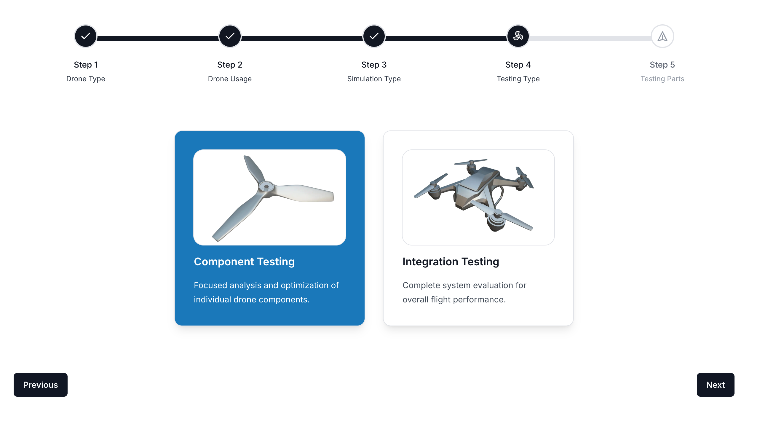
Step 5: Selecting the Testing Part
In this step, define the part of the drone that will undergo aerodynamic analysis.
- Drone Propeller: Simulates the aerodynamics and loading characteristics of the propeller.
- Drone Wing: Focuses on wing aerodynamics and structural behavior in various conditions.
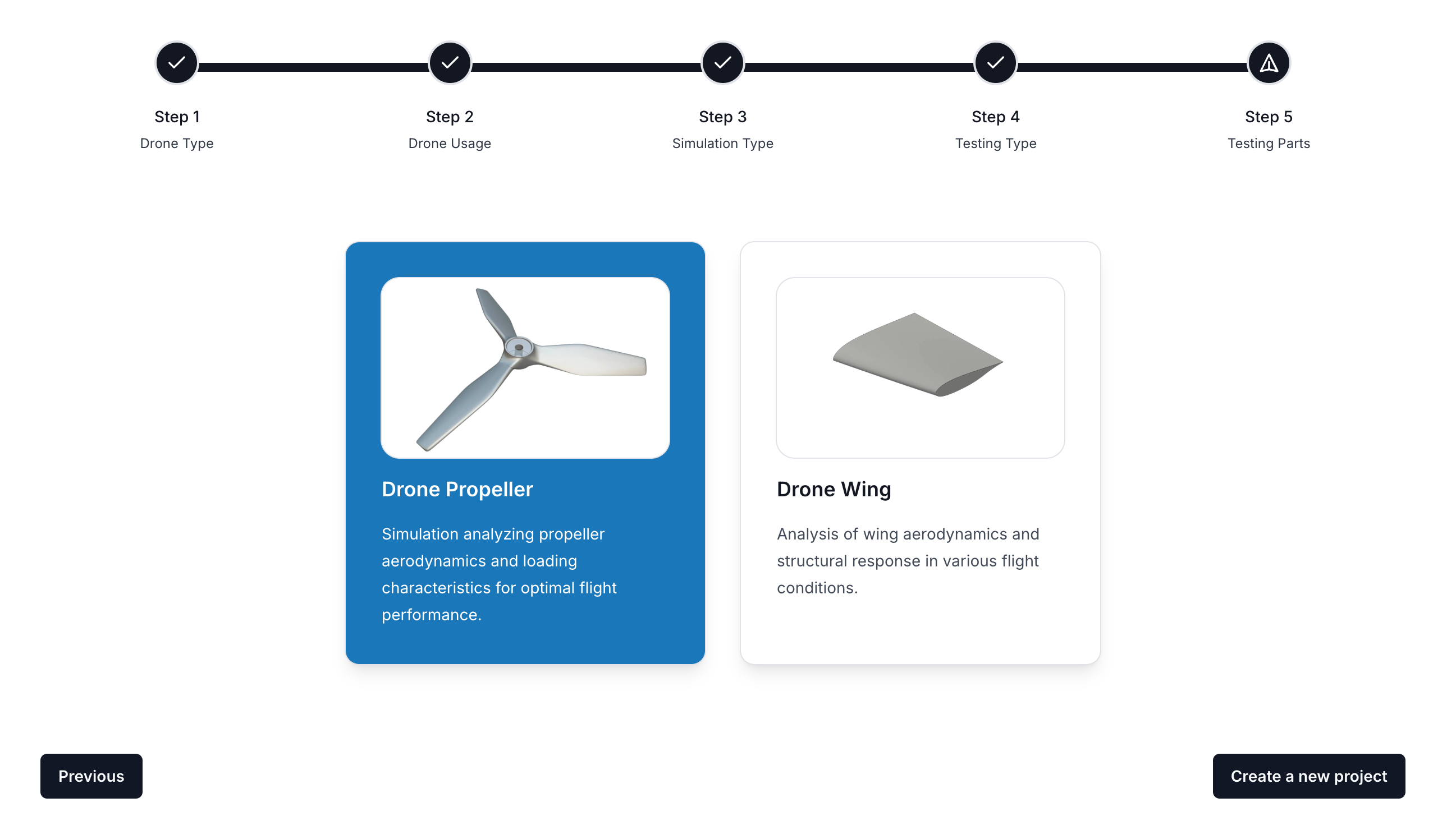
Click Next to proceed with the propeller CFD workflow.
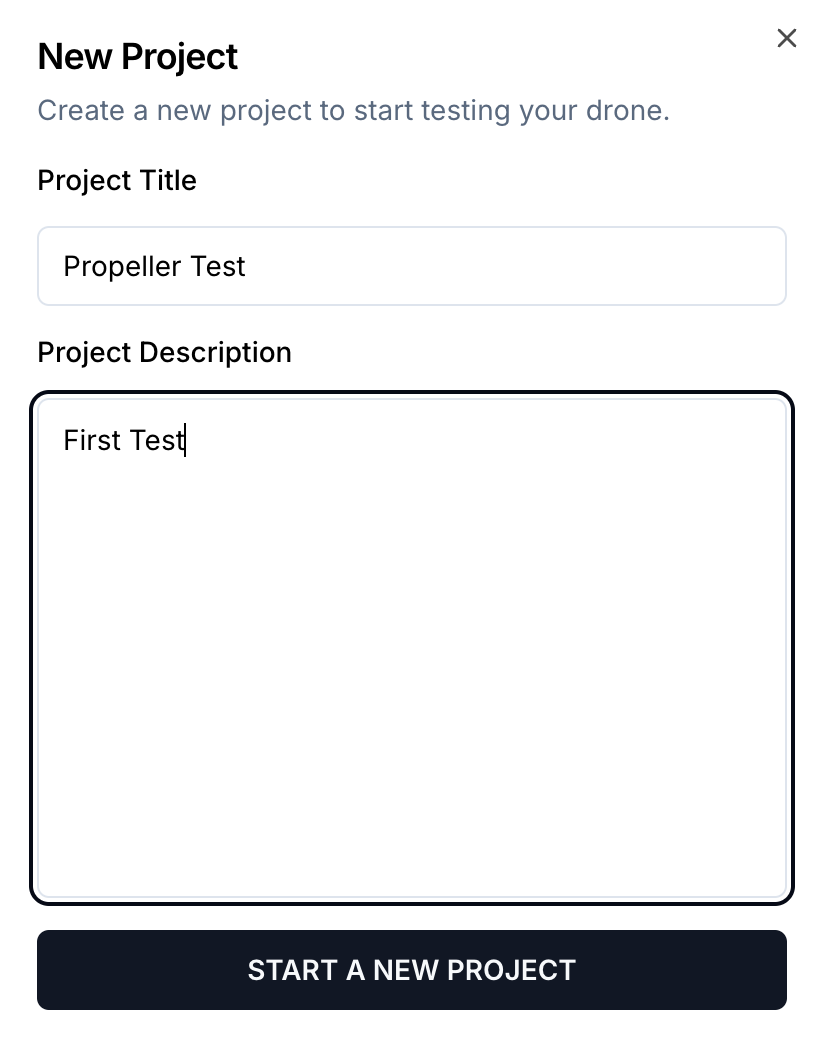
Creating a New Project
Define your project settings by entering a Project Title and Description, then click Start a New Project.
Step 6: Propeller Design Workflow
The workflow panel will now guide you through the design and analysis steps. The first step is to create the propeller geometry.

Step 7: Designing the Propeller Structure
Define the root, middle, and side sections of the propeller by adjusting the geometric parameters.
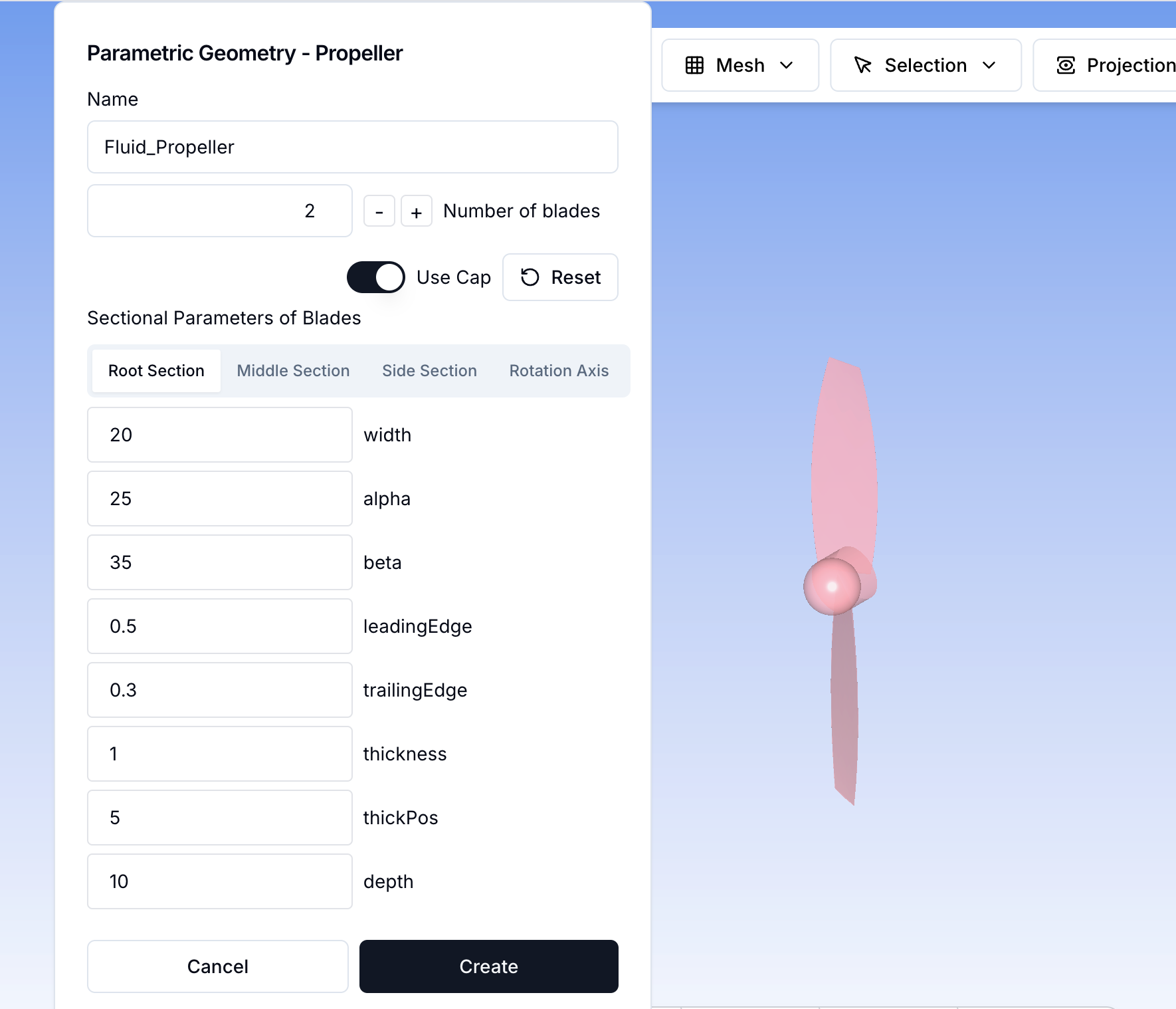
Switch to the Rotation Axis tab to define the rotational properties of the propeller.
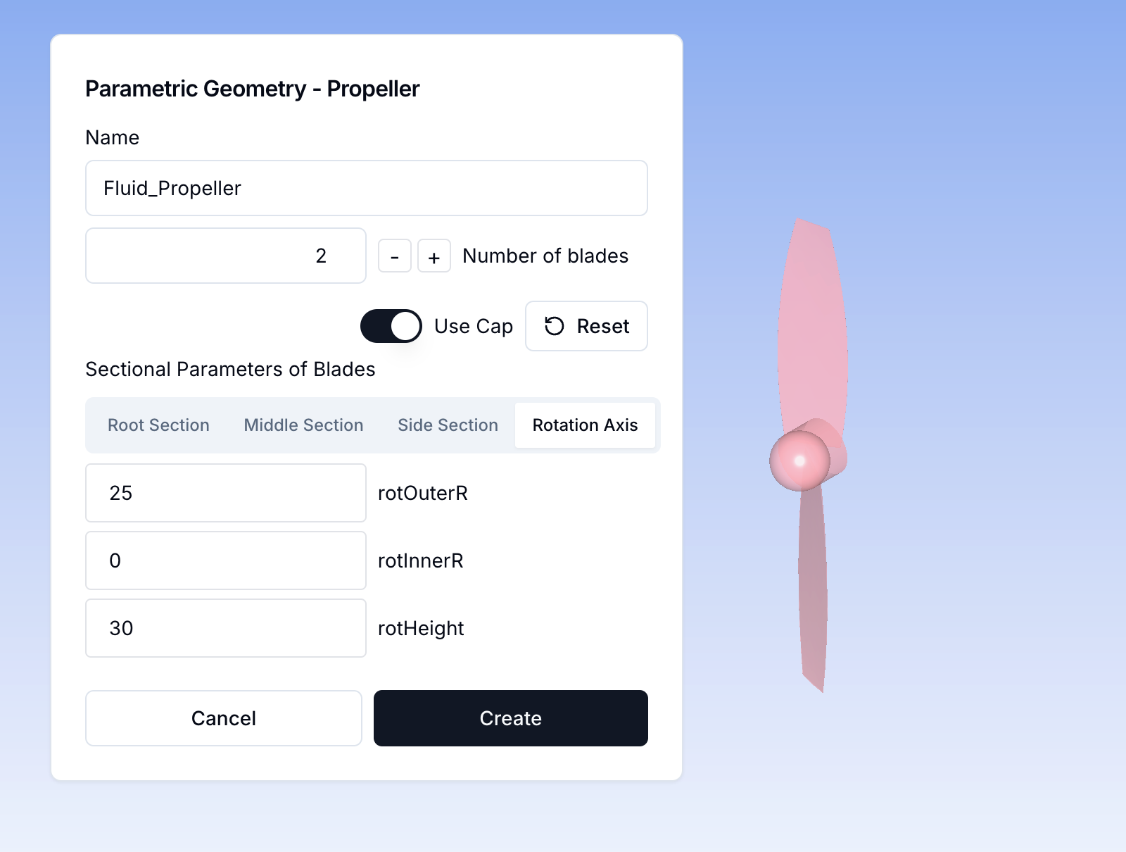
Click Create to finalize the propeller geometry.
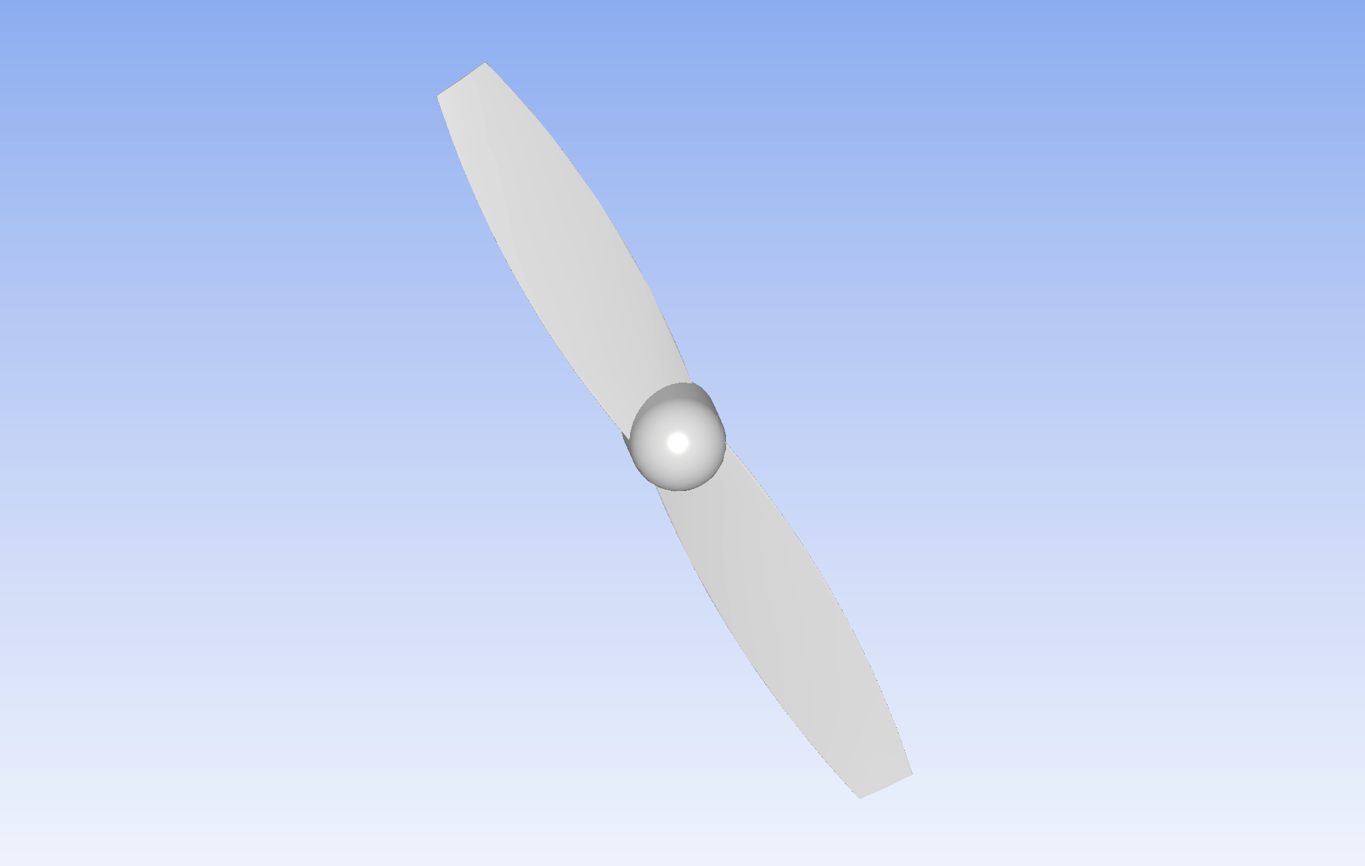
Step 8: Completing Propeller CAD
Once the propeller design is finalized, the CAD model will be generated.
Step 9: Defining the Fluid Region
Set up the inner fluid region for CFD analysis by specifying the relevant parameters.

Then, configure the outer fluid region to extend the computational domain.
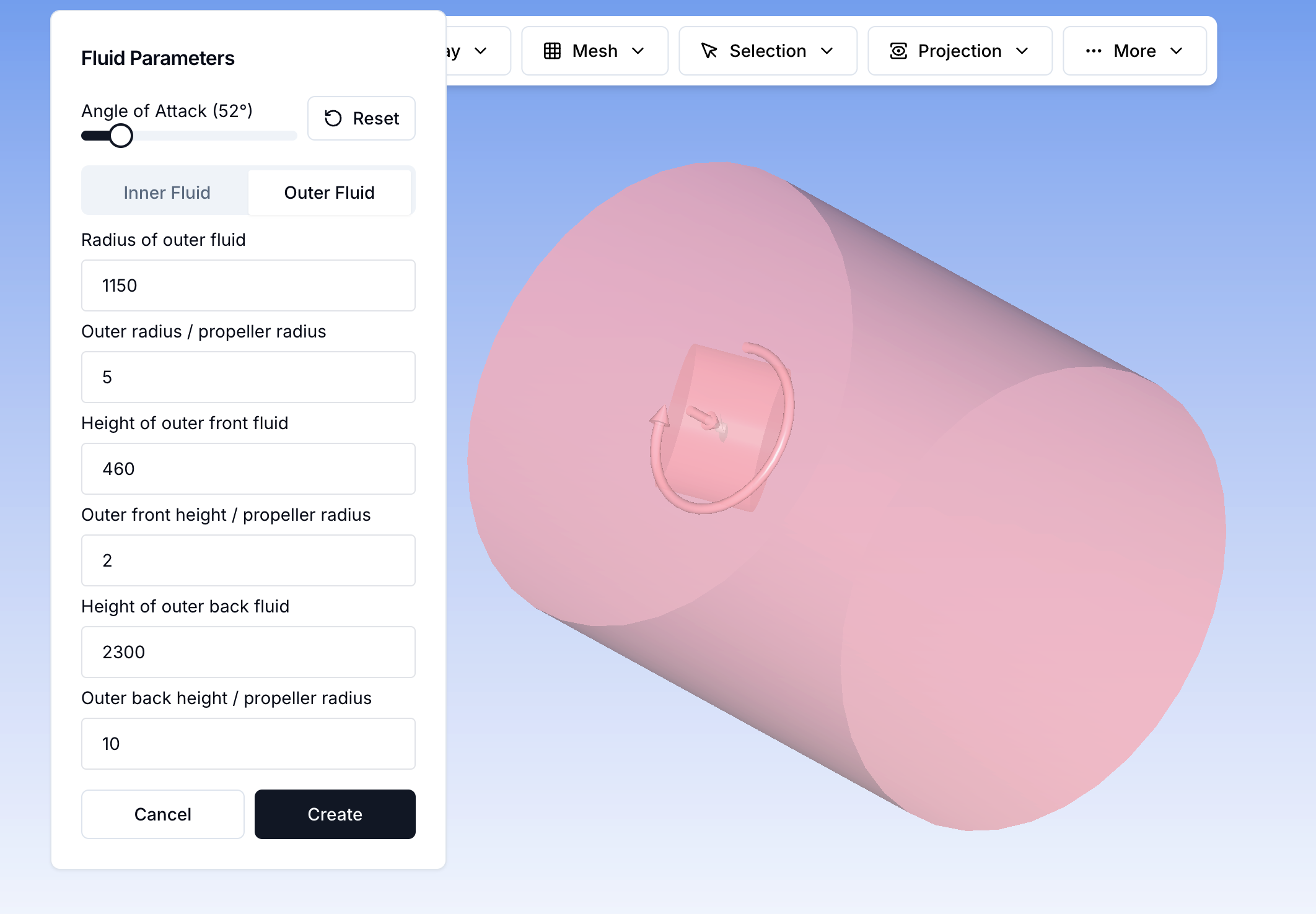
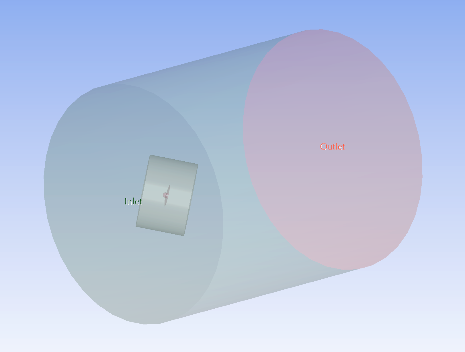
Once both regions are defined, finalize the fluid domain.
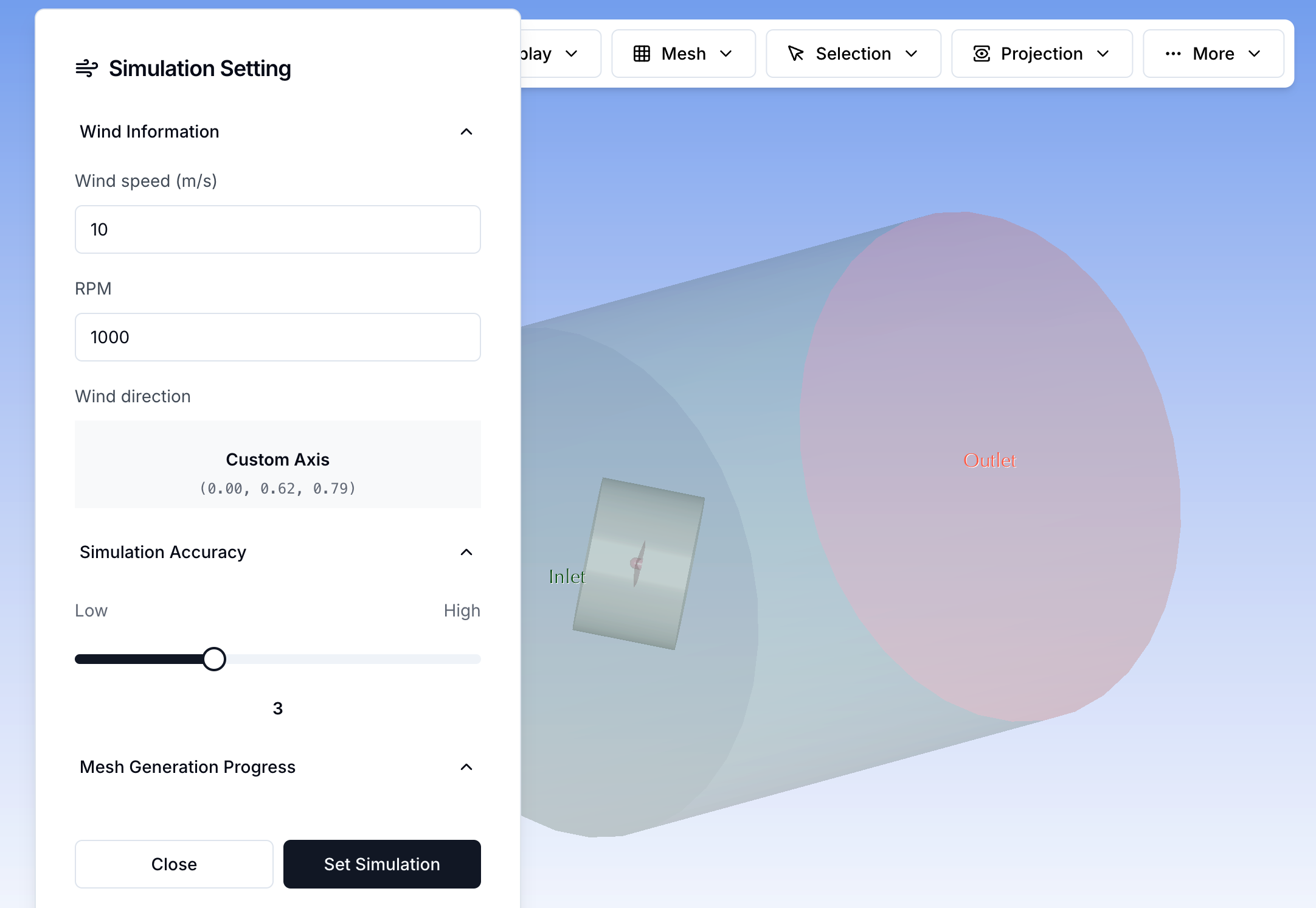
Step 10: Configuring Simulation Settings
Set the wind speed, RPM, and simulation accuracy to specify the operating conditions.
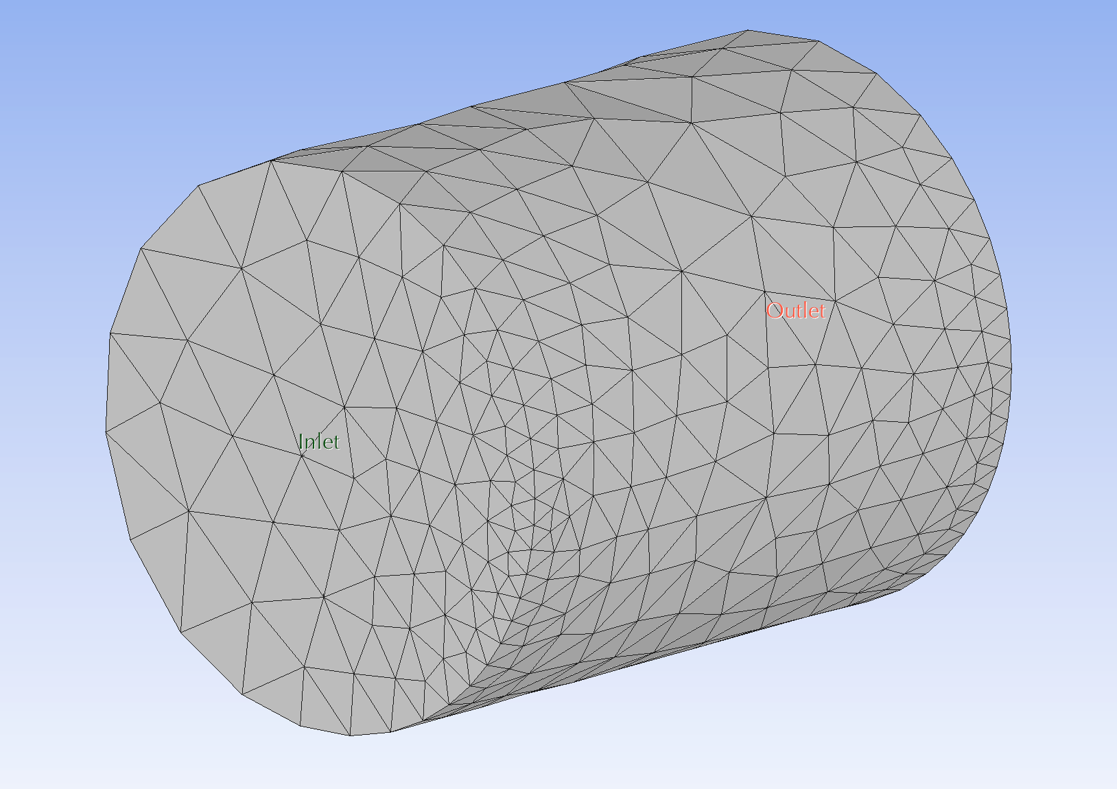
Step 11: Generating Mesh
Create the computational mesh for the simulation.
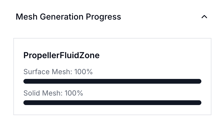
Once meshing is complete, review the final mesh quality.
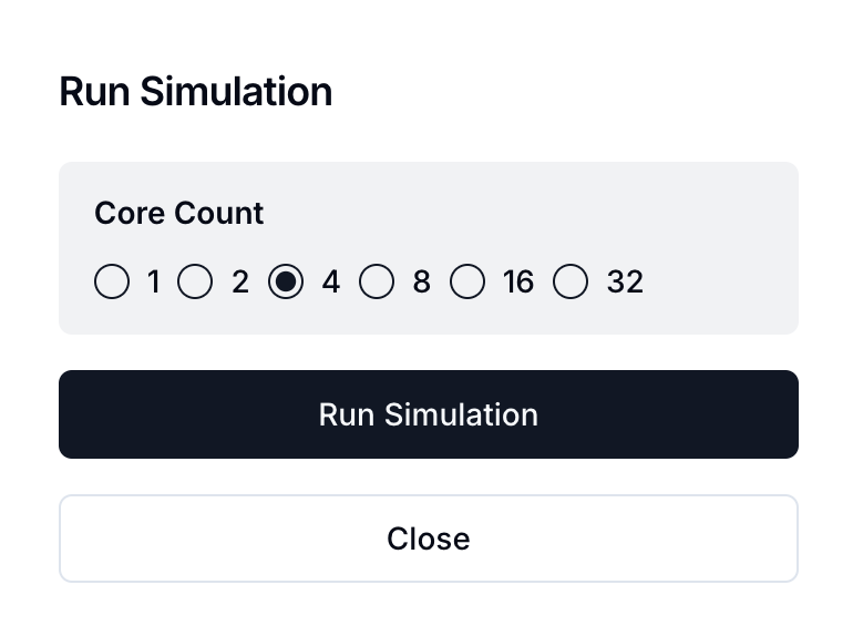
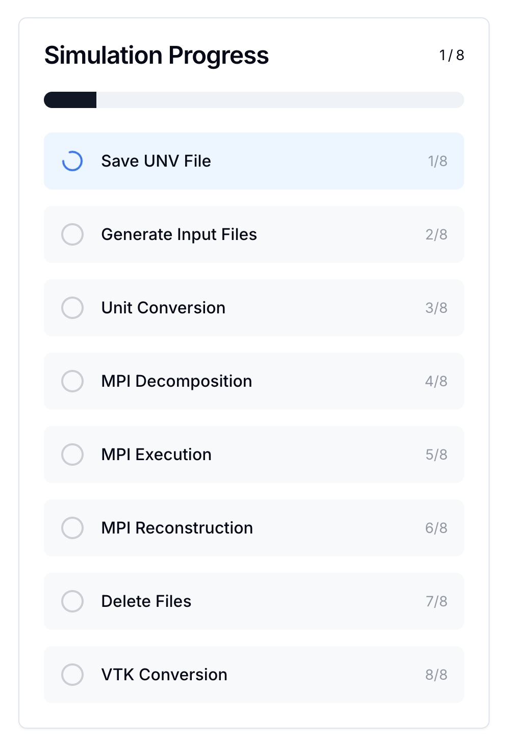
Step 12: Running the Simulation
Choose the number of CPU cores and initiate the simulation.
Monitor the progress of the simulation execution.
Final Steps
Once the simulation completes, analyze the results to evaluate the aerodynamic performance of the propeller. Proceed to visualization and data interpretation for further insights.