eVTOL: Rapid Aerodynamics
Target Aircraft Information
- Main wing span: 1.479 m
- Fuselage length: 0.915 m
- 4 hovering propellers
- Diameter: 0.24 m
- Airfoil: NACA-4412
- RPM: 4000
Download Sample STL File
Download the sample STL file to follow along with this tutorial:
Step 1: Import CAD Geometry
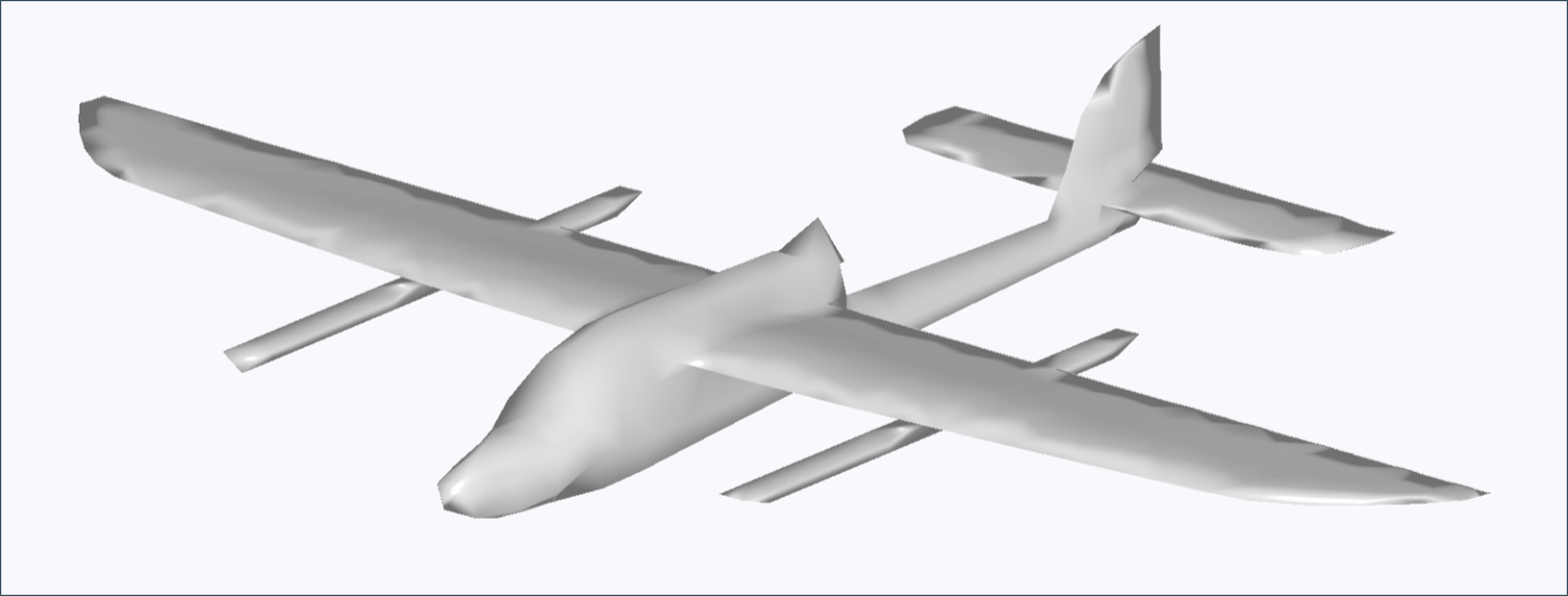
- Navigate to the Rapid Aerodynamics module
- Click the Import CAD button
- Select the
skysurfer_vortex.stlfile - Verify that the import completed successfully
Important Notes:
- STL files must contain less than 2000 surface elements
- Geometry is directly reflected in the analysis without modification
- Ensure proper scale and units before importing
Step 2: Configure Propellers
When creating multiple identical propellers, you can define the blade geometry first and then copy the propeller. This allows the blade geometry information to be copied for faster workflow.
2.1. Blade Configuration
- Select Airfoil: NACA-4412
- Number of Blades: 2
- Number of Blade Sections: 6
- Blade Section Data: Configure as follows
- Radial Position: Distance from propeller center [m]
- Chord Length: Blade width (chord line length) at this section [m]
- Twist Angle: Pitch angle of the blade section [°]
- Twist Position: Chord-wise position of twist axis (0 ~ 100)
[radius, chord, twist, twist axis]
0.005, 0.02, 12, 25
0.02, 0.03, 15, 25
0.04, 0.035, 20, 25
0.06, 0.03, 15, 25
0.08, 0.03, 10, 25
0.1, 0.02, 5, 25
0.12, 0.01, 0, 25
2.2. Propeller Placement
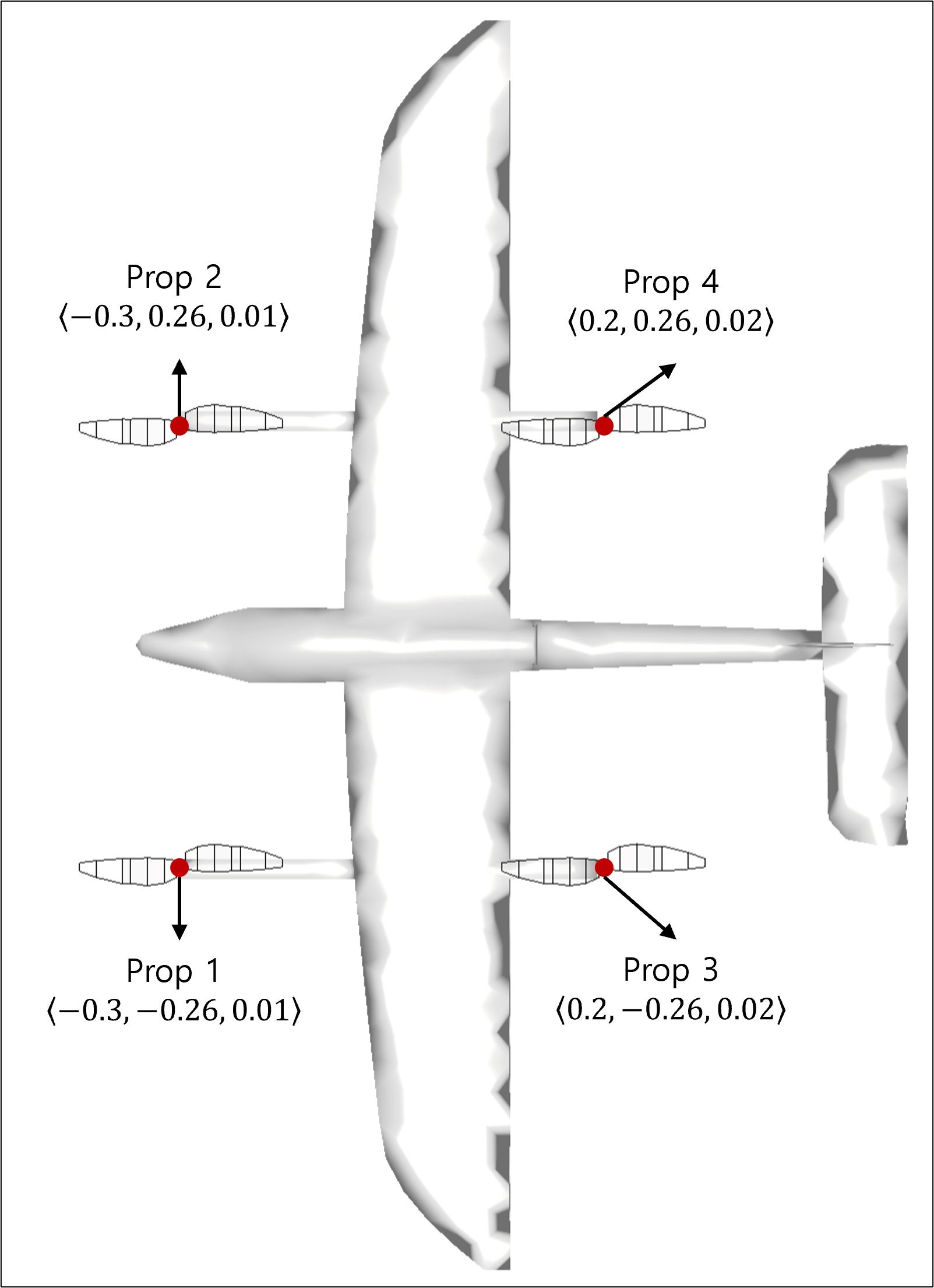
Refer to the figure above to set the propeller placement positions:
prop 1: <-0.3, -0.26, 0.01>
prop 2: <-0.3, 0.26, 0.01>
prop 3: <0.2, -0.26, 0.02>
prop 4: <0.2, 0.26, 0.02>
Step 3: Configure Simulation Settings and Run
3.1. Simulation Settings
- Simulation Style, Enable VPM: User's choice
- Flow Velocity: 0 m/s
- Number of Cores: 8 or more recommended
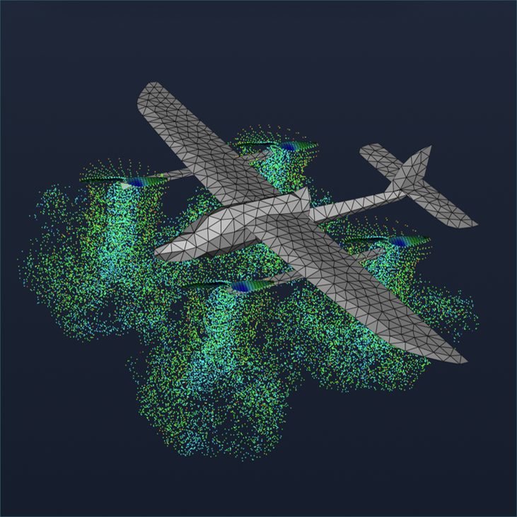
Step 4: Visualize Results
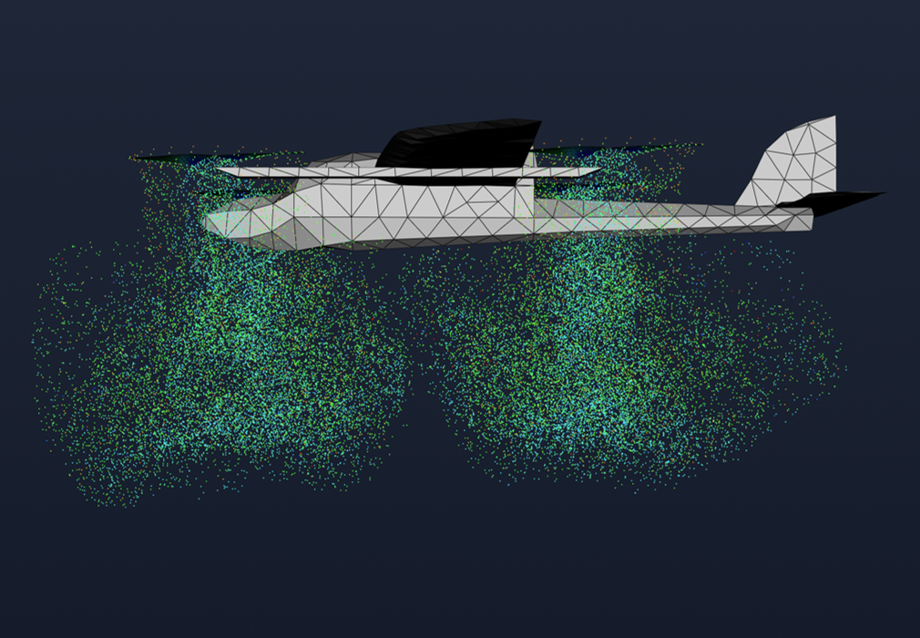
Visualization is primarily used to review whether the flow analysis results are physically reasonable. In this analysis, we mainly examine the following phenomena:
- Strong circulation at blade tips
- Flow near propellers: Helicoil-shaped flow pattern
- Flow away from propellers: Wake roll-up formation where the wake curls outward
Step 5: Review Reports
5.1. System Forces and Moments
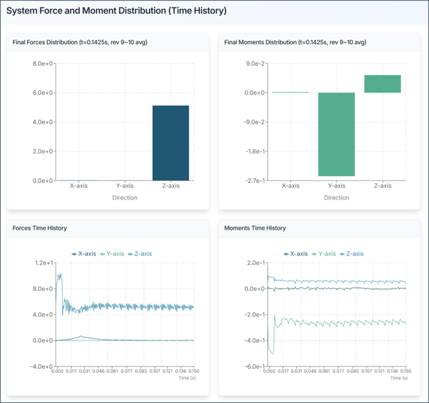
Review the forces acting on the entire aircraft:
- Fx, Fy, Fz: Forces in x, y, z directions [N]
- Mx, My, Mz: Moments about x, y, z axes [N·m]
Analysis Tips:
- Total Thrust (Fz): Should match expected lift requirements
- Moments: Should be balanced for stable flight
5.2. Propeller Performance
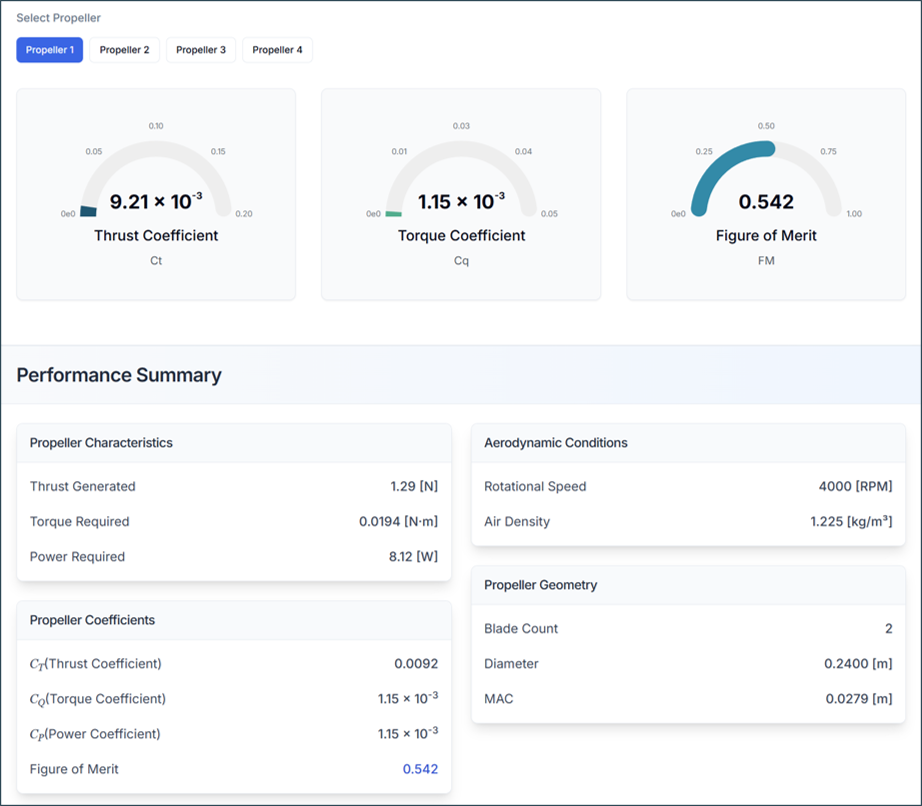
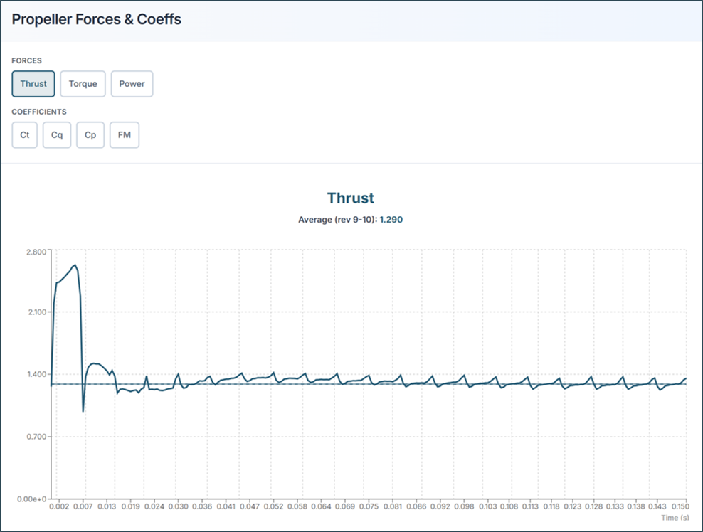
Thrust Coefficient (Ct)
- Higher Ct = more thrust per revolution
- Typical range: 0.08 - 0.15
Torque Coefficient (Cq)
- Represents power requirement
- Lower Cq = more efficient
Power Coefficient (Cp)
- Indicates power consumption
- Related to motor requirements
Figure of Merit (FM)
- FM must be < 1.0
- Typical range: 0.6 - 0.85
- Higher FM = more efficient propeller
5.3. Sectional Load Distribution
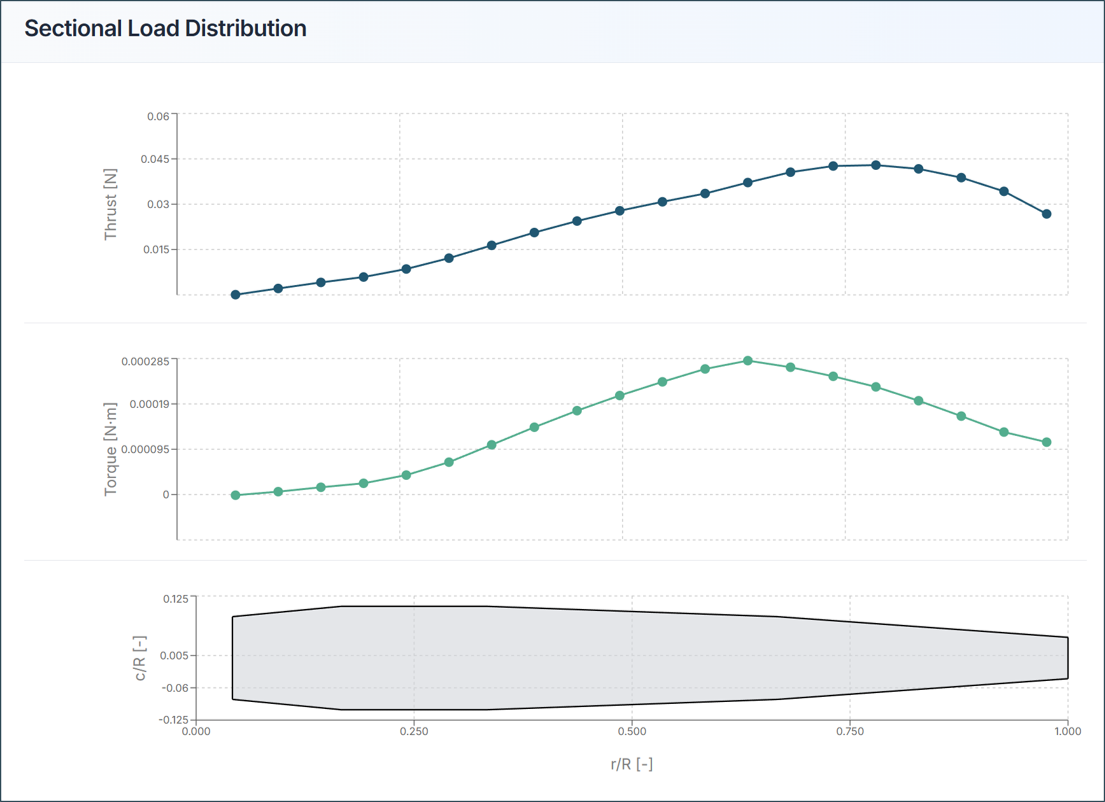
Thrust Distribution Graph:
- X-axis: Radial position (0 = hub, 1 = tip)
- Y-axis: Local thrust
- Ideal: Smooth curve with peak near blade mid-span
Torque Distribution Graph:
- Shows power requirement along blade
- Helps identify high-load regions
- Useful for structural design
Design Insights:
- Peak loads at 70-80% radius: Good design
- High tip loads: Risk of tip stall
- Uneven distribution: Consider blade redesign
Aircraft Design Tips and Troubleshooting
1) If Thrust is Insufficient
- Increase RPM
- Add more blades
- Increase blade chord length
- Increase twist angle
2) If Propeller Efficiency is Low
- Optimize blade twist distribution
- Reduce tip losses with winglets
- Improve airfoil selection
- Reduce blade interference
3) If Aircraft Moments or Forces Show Stability Issues
- Balance propeller forces
- Adjust propeller positions
- Verify moment distribution
- Check symmetric configuration
4) STL Import Failure
- Solution: Verify STL has < 2000 elements and proper format
5) Analysis Takes Too Long
- Solution: Use "Fast" mode, reduce blade sections, disable VPM
6) Results Appear Unrealistic
- Solution: Verify flow velocity + tip speed < Mach 0.7, check propeller configuration
7) Figure of Merit > 1.0
- Solution: Re-check input parameters, flow conditions, or RPM settings
Need Assistance or Have Questions?
Frequently Asked Questions: FAQ Link
Support Inquiries: support@everysim.io