Advanced Simulation Overview
Advanced Simulation, provides more reliable and meaningful results through engineering simulation technologies (CAE), including Structural Analysis(FEA), Fluid Dynamics(CFD) and Vortex Method.
1. New Project
To begin using Advanced Simulation for the first time, go to New Project and follow the steps below to properly perform your desired analysis.
1.1. Simulation Type
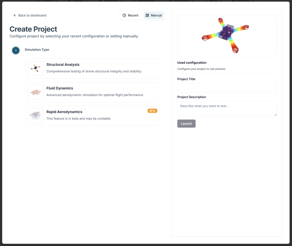
Select the type of analysis to run:
- Structural Analysis
Generates a mesh for 3D structures and analyzes stress distribution and deformation under static load conditions. Supports brep and step file formats, and can analyze compsolids consisting of multiple solids. - Fluid Dynamics
Generates a mesh for 3D fluid domains and evaluates aerodynamic characteristics using a Reynolds Averaged Navier-Stokes (RANS) equation-based solver. When importing CAD, supports brep, step, and stl file formats, assuming a single solid. - Rapid Aerodynamics
Evaluates aerodynamic characteristics using a Vortex Method solver on surface meshes for unsteady conditions. When importing CAD, uses stl file format, and the stl file cannot exceed 2,000 surface mesh elements.
Currently, Rapid Aerodynamics is in beta version, so the service may be unstable.
1.2. Testing Type
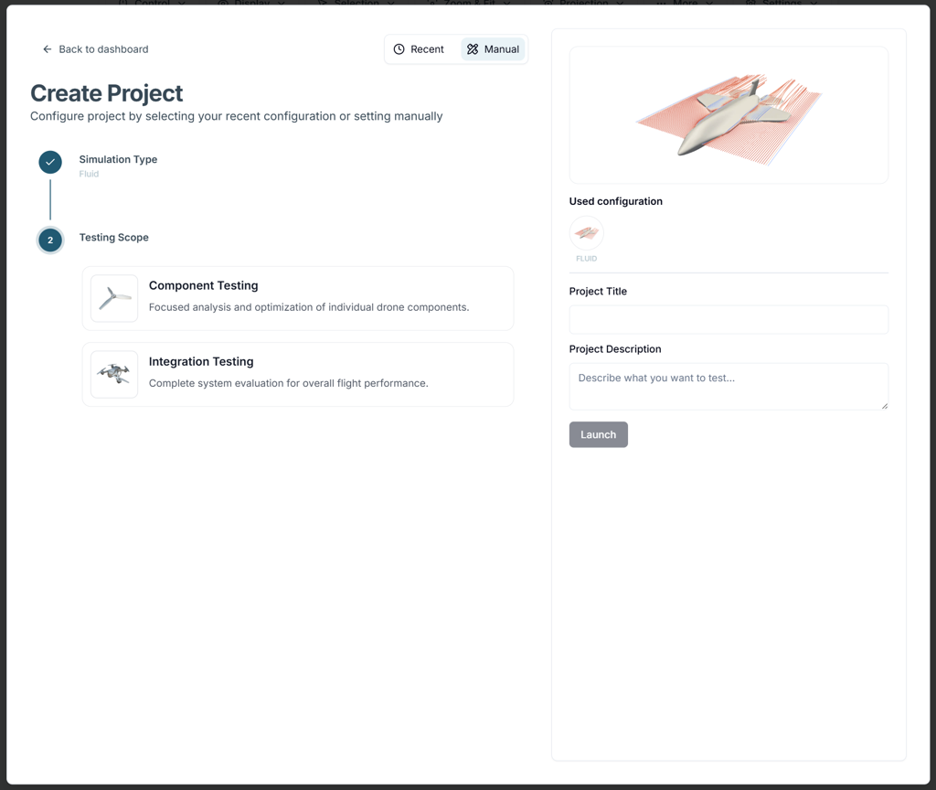
Select the test level:
- Component Testing
Provides services tailored for analyzing single components such as propellers and wings. - Integration Testing
Provides integrated or complex analysis services.
1.3. Testing Parts
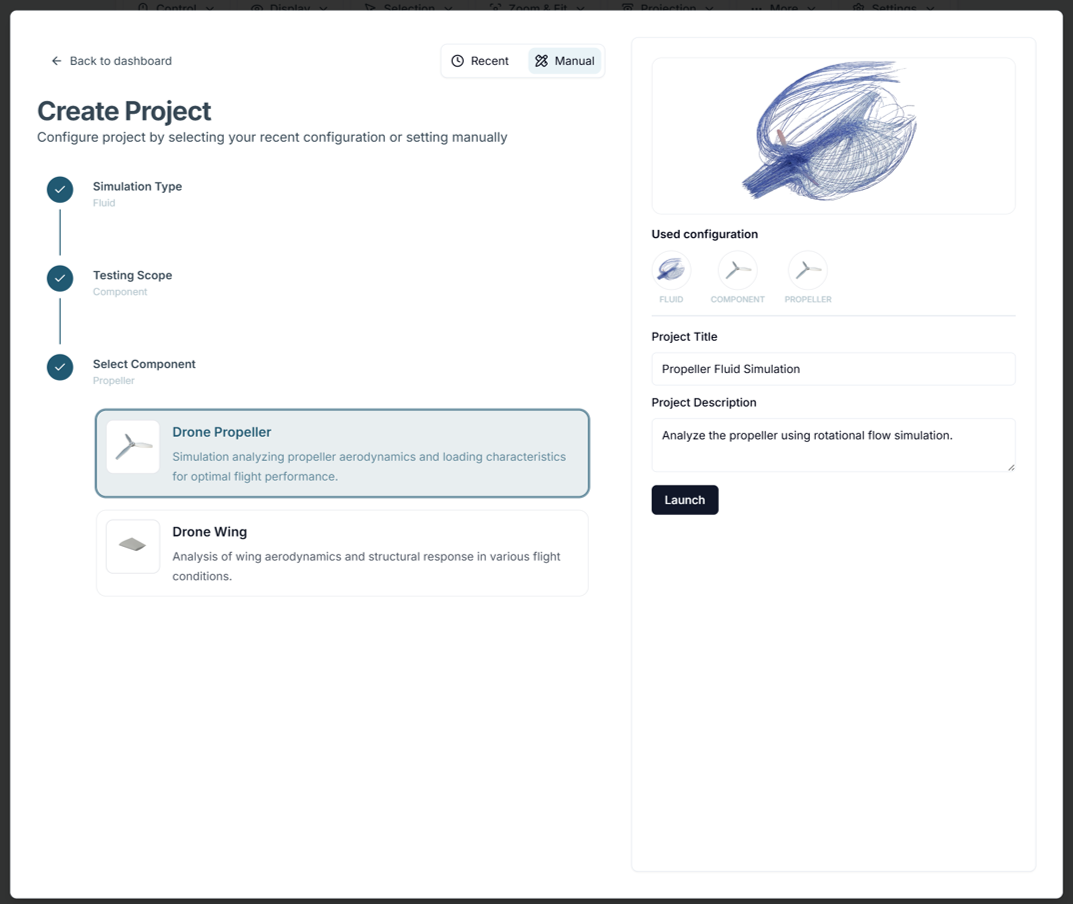
Component Testing
- Propeller, Wing: Focuses on evaluating the performance of components based on geometry, material selection, and aerodynamic characteristics.
Integration Testing
-
Aircraft (Integration): Run a comprehensive simulation on the entire drone assembly.
-
Custom Settings(Integration): Handpick the parts or subsystems you want to simulate.
After selecting your parts, proceed to set up material properties, boundary conditions, and other parameters.
1.4. New Project Name and Description
Finally, enter project tile and description, and click Launch.
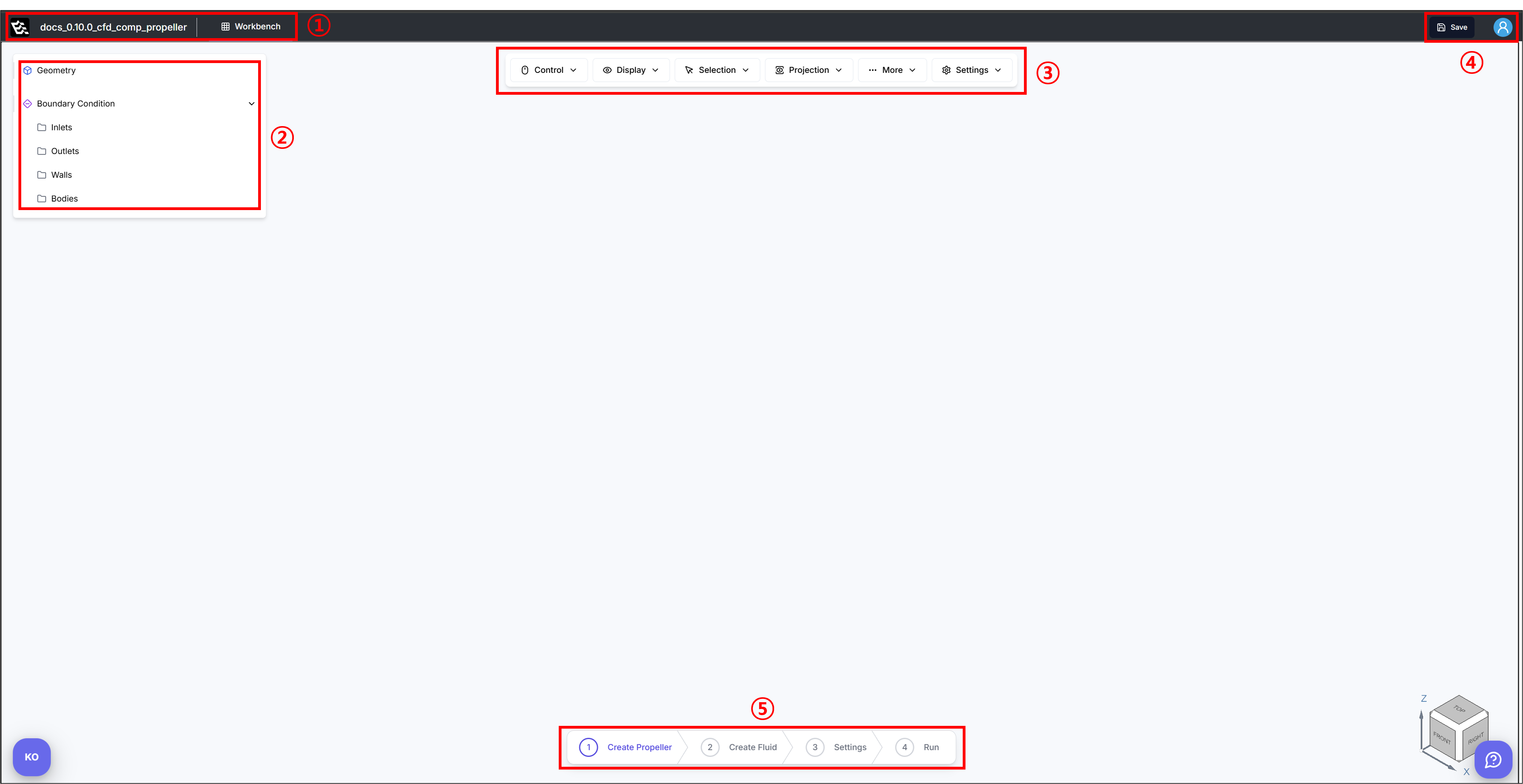
2. Workbench
When a project is created or opened, the Workbench screen is displayed. The details of this screen are described below.
2.1. Workbench Overview
-
1) Project Name and Workbench Indicator: Displays the name of the currently opened project along with the active workbench.
-
2) Geometry and Boundary Condition Model Tree: Provides a hierarchical view of the model components, including geometry and boundary conditions. For detailed information, please refer to the documentation specific to the part you intend to design.
-
3) Toolbar Panel: Provides essential controls for interacting with the 3D viewer. A detailed explanation of the toolbar functions is provided in Section 2.2. Toolbar Panel.
-
4) Save and User Account: This panel allows users to save their progress and access user account options. It ensures data is not lost and provides access to user-related preferences or login status.
-
5) Workflow Panel: Offers a guided workflow for CFD/FEA setup through a series of sequential steps. For detailed information, please refer to the documentation specific to the part you intend to design.
2.2 Toolbar Panel
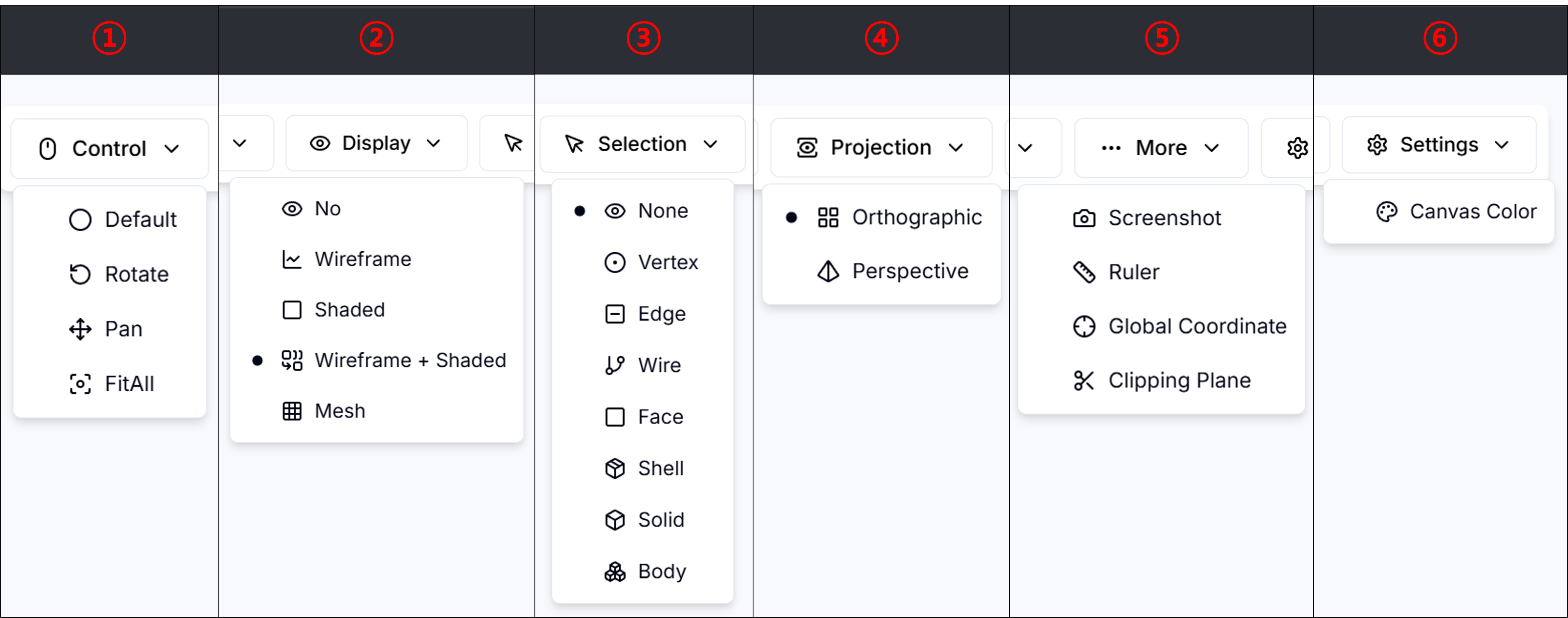
The Toolbar Panel provides essential tools for controlling the 3D viewer environment. It includes six main categories of functions, each described below:
1) Control: Offers basic interaction modes for navigating the 3D scene.
- Default: Resets to the default interaction mode.
- Rotate: Enables view rotation.
- Pan: Moves the view along the screen plane.
- FitAll: Fits all visible objects into the viewport.
2) Display: Controls how the geometry is visualized in the 3D view.
- No: Hides the object.
- Wireframe: Displays geometry as wireframe lines.
- Shaded: Displays shaded surfaces.
- Wireframe + Shaded: Overlays wireframe lines on shaded surfaces.
- Mesh: Visualizes the underlying mesh structure.
3) Selection: Specifies the type of elements selectable in the viewport.
- None: Disables selection.
- Vertex: Enables selection of points or vertices.
- Edge: Enables selection of edges.
- Wire: Enables selection of wireframe elements.
- Face: Enables selection of surface faces.
- Shell: Enables selection of shell-type geometry.
- Solid: Enables selection of solid volumes.
- Body: Enables selection of entire geometric bodies.
4) Projection: Sets the projection mode of the 3D viewer.
- Orthographic: Uses orthographic projection (no perspective distortion).
- Perspective: Uses perspective projection (objects appear smaller with distance).
5) More: Provides additional tools for viewer interaction and measurement.
- Screenshot: Captures a screenshot of the current view.
- Ruler: Activates a tool to measure distances.
- Global Coordinate: Displays global coordinate axes.
- Clipping Plane: Enables slicing the model with a clipping plane.
6) Settings: Adjusts general viewer appearance.
- Canvas Color: Changes the background color of the viewer.
3. Link to Detailed Design Settings
Access the following link to review the information required to perform your desired analysis.
3.1. Structural Analysis(FEA)
Component
Integration
3.2. Fluid Dynamics(CFD)
Component
Integration
3.3. Rapid Aerodynamics(VM)
Component
Integration
Need Assistance or Have Questions?
Frequently Asked Questions: FAQ Link
Support Inquiries: support@everysim.io