4.13 Rapid Aerodynamics: Integration-Propeller Based
1. Import CAD
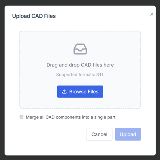
Import the stl CAD file to be analyzed. The stl file is limited to less than 2000 surface elements, and the stl file geometry is reflected directly in the analysis.
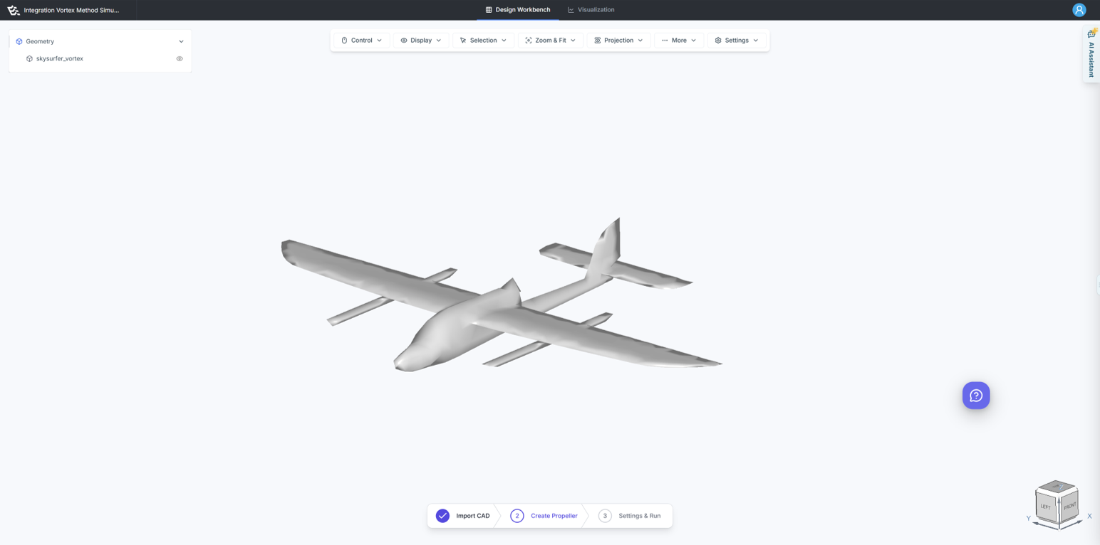
After executing the import, verify on the canvas that the CAD has been loaded correctly.
2. Create Propeller
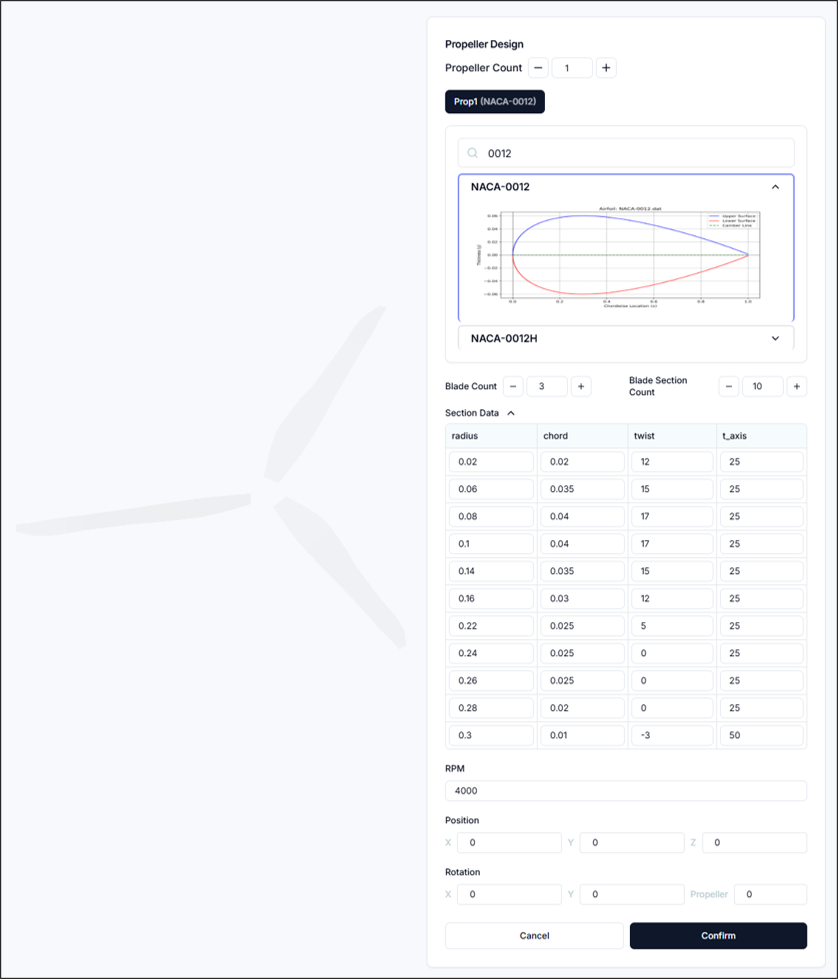
Multiple propellers can be created and configured individually. The configuration process is as follows:
2.1. Set and Select Number of Propellers
- Number of Propellers: You can increase or decrease the number of propellers, and corresponding buttons will be created below for each propeller.
2.2. Airfoil Configuration
Search and select the desired airfoil, which will serve as the basis for the propeller geometry.
2.3. Blade Configuration
- Number of Blades: Sets the number of blades on the propeller.
- Number of Blade Sections: Sets the number of cross-sections per blade.
- Section Data: Configure the blade geometry through
<Radial Position, Chord Length, Twist Angle, Twist Position>settings.
2.4. RPM Configuration
- RPM: Sets the propeller RPM.
2.5. Position and Rotation Configuration
- Position: Sets the position of the propeller center as
<x, y, z>. - Rotation: Rotates the propeller's axis direction based on
<x, y>axes, and sets the initial rotation angle around the propeller center.
3. Setup & Run
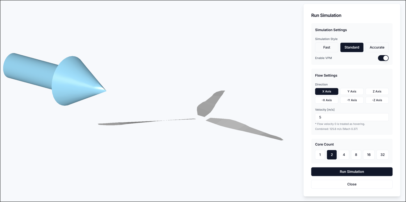
In the Simulation Run step, configure the flow and simulation settings, then execute the analysis.
3.1. Simulation Settings
- Simulation Style: Select one of Fast/Standard/Accurate. When Fast is selected, VPM is always disabled.
- Enable VPM: You can enable or disable the Vortex Particle Method.
3.2 Flow Settings
- Flow Direction: Specifies the direction of flow. The specified direction can be visually confirmed as a blue arrow on the canvas.
- Flow Velocity: Sets the flow velocity. The combined velocity with the tip speed based on RPM must not exceed Mach 0.7, and when set to 0, hovering is assumed.
3.3 Core Settings
- Number of Cores: Sets the number of CPUs to use for analysis execution.
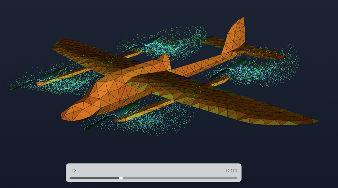
After completing the configuration, starting the analysis will execute it as shown in the figure.
4. Result
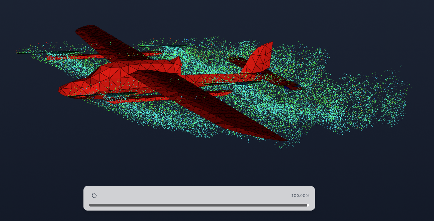 In the Result section, you can visualize circulation (circ) and pressure coefficient (Cp) as 3D contours.
5. Report
This section allows you to evaluate aircraft performance based on numerical data derived from simulation results.
5.1. System Force/Moment Distribution
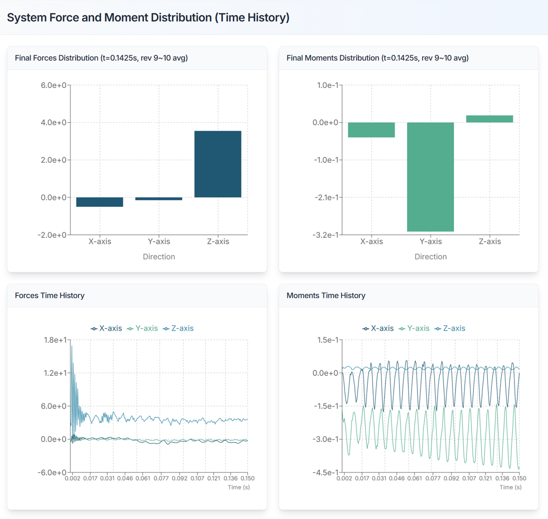
- Displays information about the total force and moment distribution (6-component forces).
5.2. Propeller Performance Analysis
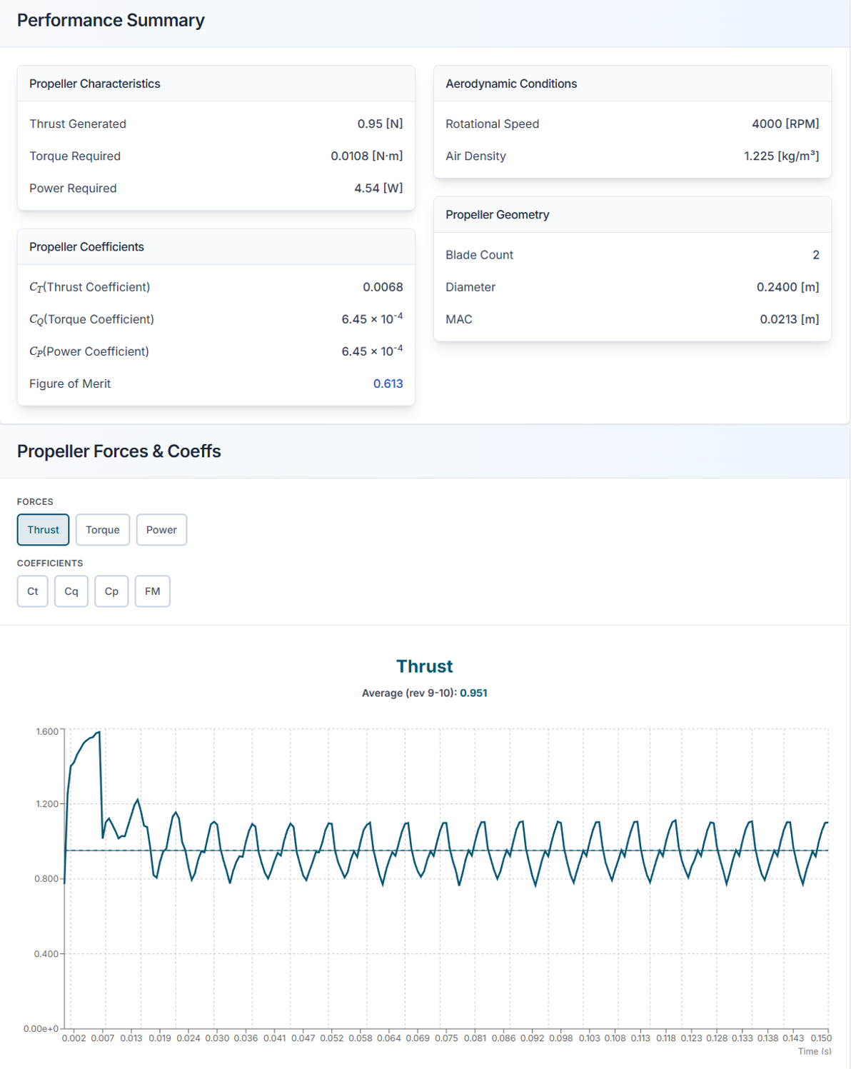
Displays aerodynamic performance and condition information for each propeller. The coefficients are defined as follows:
- Thrust Coefficient: Dimensionless thrust generated by the propeller
- Torque Coefficient: Dimensionless torque required for propeller rotation
- Power Coefficient: Performance indicator of the power required for propeller rotation in dimensionless form
- Figure of Merit: Dimensionless number indicating propeller efficiency; the figure of merit must always be less than 1
Sectional Load Distribution
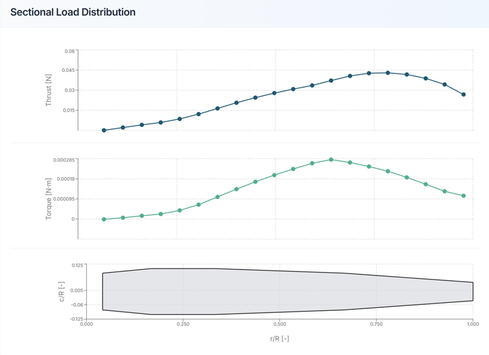
Graphically displays the thrust and torque distribution acting on each section of the propeller blade.
Need Assistance or Have Questions?
Frequently Asked Questions: FAQ Link
Support Inquiries: support@everysim.io